Anti-seepage drainage structure and construction method thereof

A drainage structure, anti-penetration technology, applied in infrastructure engineering, construction, liquid/vacuum measurement for liquid tightness, etc.

Active Publication Date: 2021-11-05
上海北横建设工程有限公司
View PDF5 Cites 1 Cited by
  • Summary
  • Abstract
  • Description
  • Claims
  • Application Information

AI Technical Summary

Problems solved by technology

[0005] Existing, especially with the application of prefabricated buildings, prefabricated buildings are mostly waterproofed in the form of waterproof and waterproof coatings in bathrooms. Due to the problems of building assembly and later use and disassembly, it is easy to cause the waterproof layer to break and leak, and seepage Leaked water is easy to cause damage to the building and the lower buildings, and the leakage of the waterproof layer is difficult to find leaks due to the decorations such as floor tiles attached to the surface of the waterproof layer, and it is time-consuming and laborious to remove the decorations and repair them.

Method used


Image

  • Anti-seepage drainage structure and construction method thereof
  • Anti-seepage drainage structure and construction method thereof
  • Anti-seepage drainage structure and construction method thereof

Examples


Embodiment 1

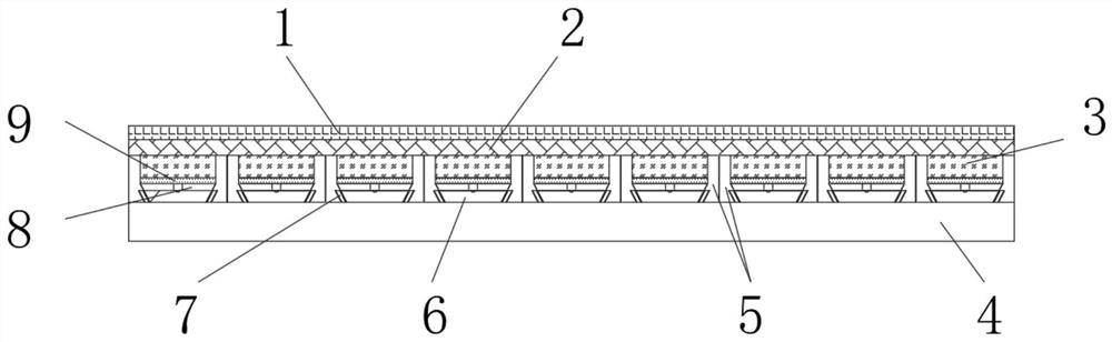
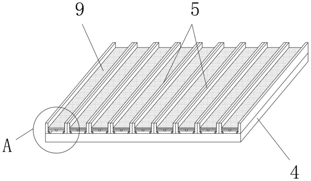
[0042] like figure 1 As shown, a kind of anti-seepage drainage structure includes a building base plate 4, the upper end surface of the building base plate 4 is fixedly connected with an anti-seepage frame 5, and the middle part of the anti-seepage frame 5 is embedded with a water-collecting groove 6, and the water-collecting groove 6 The upper end surface is fixedly connected with a support frame 8, and the upper end surface cover of the support frame 8 is provided with a partition plate 9, and the support frame 8 and the partition plate 9 are located inside the anti-seepage frame 5, between the partition plate 9 and the anti-seepage frame 5 The upper part of the gap between them is filled with a structural layer 3, the upper end surface of the structural layer 3 is level with the upper end surface of the anti-seepage frame 5, the upper end surface of the structural layer 3 is coated with a waterproof layer 2, and the upper end surface of the waterproof layer 2 is installed wi...

Embodiment 2

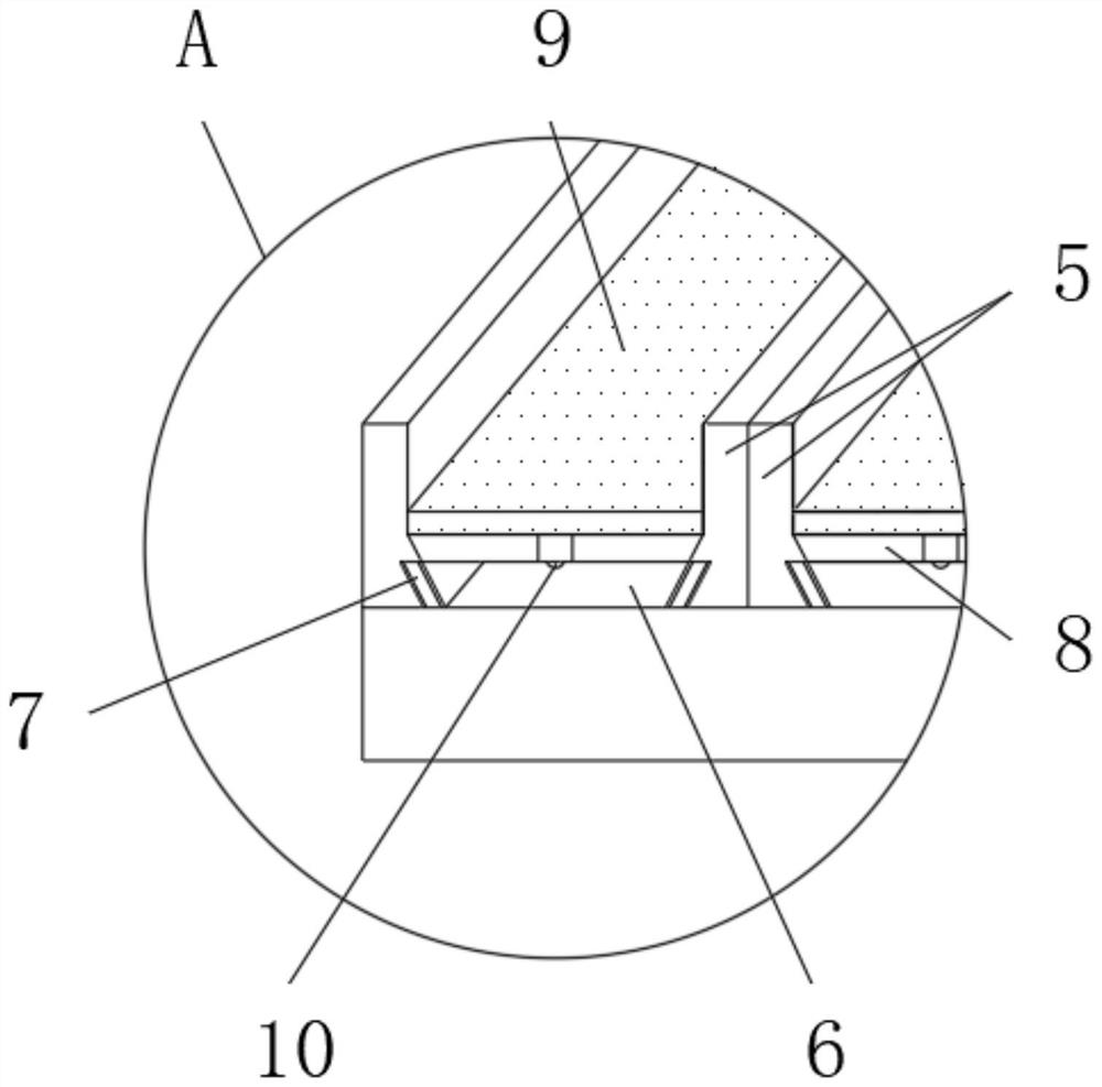
[0045] like Figure 1-3 As shown, the inner wall of the water-collecting embedding groove 6 is inclined, and the water-collecting embedding groove 6 is funnel-shaped.

[0046] During use, by setting the inner wall of the water-collecting groove 6 into an inclined state, it is convenient to infiltrate moisture in the waterproof layer 2 along the anti-seepage frame 5 and

[0047] The inner wall of the water collection embedding groove 6 stays and gradually gathers.

[0048] like Figure 1-6 As shown, the bottom of the water-collecting groove 6 is fixedly connected with a drain pipe 11, and the end surface of the drain pipe 11 and the water-collecting groove 6 is fixedly connected with an extension rod 12, and the middle part of the lower end surface of the extension rod 12 is fixedly connected with a second collecting protrusion. 13, and the lower end surface of the support frame 8 is fixedly connected with the first collector protrusion 10, the first collector protrusion 10 a...


PUM


Abstract

The invention discloses anti-seepage drainage structure and a construction method thereof. The anti-seepage drainage structure comprises a building bottom plate, an anti-seepage frame is fixedly connected to the upper end face of the building bottom plate, a water collecting caulking groove is formed in the middle of the anti-seepage frame in an embedded mode, and a supporting frame is fixedly connected to the upper end face of the water collecting caulking groove; a partition plate covers the upper end face of the supporting frame, and the supporting frame and the partition plate are located in the anti-seepage frame; the upper part of a gap between the partition plate and the anti-seepage frame is filled with a structural layer, the upper end face of the structural layer is parallel to the upper end face of the anti-seepage frame, and the upper end face of the structural layer is coated with a waterproof layer; and a decorative layer is mounted on the upper end face of the waterproof layer, the waterproof layer is sprayed to the inner wall of the anti-seepage frame and the inner wall of the water collecting caulking groove, an indication belt is slidably connected into the anti-seepage frame, the indication belt is attached to the water collecting caulking groove, and the indication belt is used for detecting moisture in the water collecting caulking groove.

Description

technical field [0001] The invention relates to the technical field of construction, in particular to an anti-seepage drainage structure and a construction method thereof. Background technique [0002] Waterproof layer: a material layer designed to prevent indoor water, other water or groundwater from entering the roof, penetrating into walls, basements and underground structures, and penetrating into floors and walls. [0003] The requirements for an ideal waterproof layer can be simply summarized as impermeable after construction and impermeable within the design period, and it is economical. This requires that the waterproof layer not only maintains good integrity, but also has a certain ability to resist external damage. [0004] Chinese Invention Patent Publication No. CN111560990A, the present invention relates to the technical field of anti-seepage water drainage structure, and discloses a basement anti-seepage water drainage structure, including a base plate, on whi...

Claims


Application Information

Patent Timeline
Patent Type & Authority Applications(China)
IPC IPC(8): E02D31/02E02D31/00G01M3/04
CPCE02D31/02E02D31/004G01M3/04
Inventor 曾兵王德咏王婧
Owner 上海北横建设工程有限公司
Why Eureka
Try Eureka