Device suitable for placing memory banks in memory slot of mainboard in batches

A technology for memory slots and memory sticks, which is applied in the fields of instruments, electrical digital data processing, and digital data processing components, etc., can solve the problems of increasing the scrap rate of memory stick production, increasing hidden dangers in quality, and increasing labor costs, so as to eliminate material scrapping. Or there are quality problems, the effect of reducing labor costs and product production costs, and improving assembly production efficiency

Active Publication Date: 2021-11-05
INSPUR SUZHOU INTELLIGENT TECH CO LTD
View PDF4 Cites 3 Cited by
  • Summary
  • Abstract
  • Description
  • Claims
  • Application Information

AI Technical Summary

Problems solved by technology

like figure 1 and figure 2 As shown, because the distance between the memory slots on each motherboard is not necessarily equal to the distance between the memory on the tray, the installation process can only transfer the memory sticks from the tray to the memory slots on the motherboard one by one, instead of batching them all at once. Multiple memory sticks are transferred to the mainboard memory slot
[0003] This installation method not only has low production efficiency, but also increases labor costs.
When installing server products, sometimes a machine needs to be inserted with 20 or 30 memory sticks. In this case, the inefficiency is particularly obvious.
Moreover, when manually picking and placing the memory sticks, they may touch the electronic materials on the memory sticks, causing collisions or sweat stains, which will increase the production scrap rate of memory sticks and reduce product reliability.
The above problems will increase the cost of the product and increase the hidden dangers of quality. If it is serious, it will lead to the scrapping of the machine or customer complaints.

Method used


Image

  • Device suitable for placing memory banks in memory slot of mainboard in batches
  • Device suitable for placing memory banks in memory slot of mainboard in batches
  • Device suitable for placing memory banks in memory slot of mainboard in batches

Examples


Embodiment

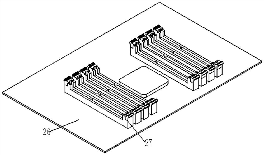
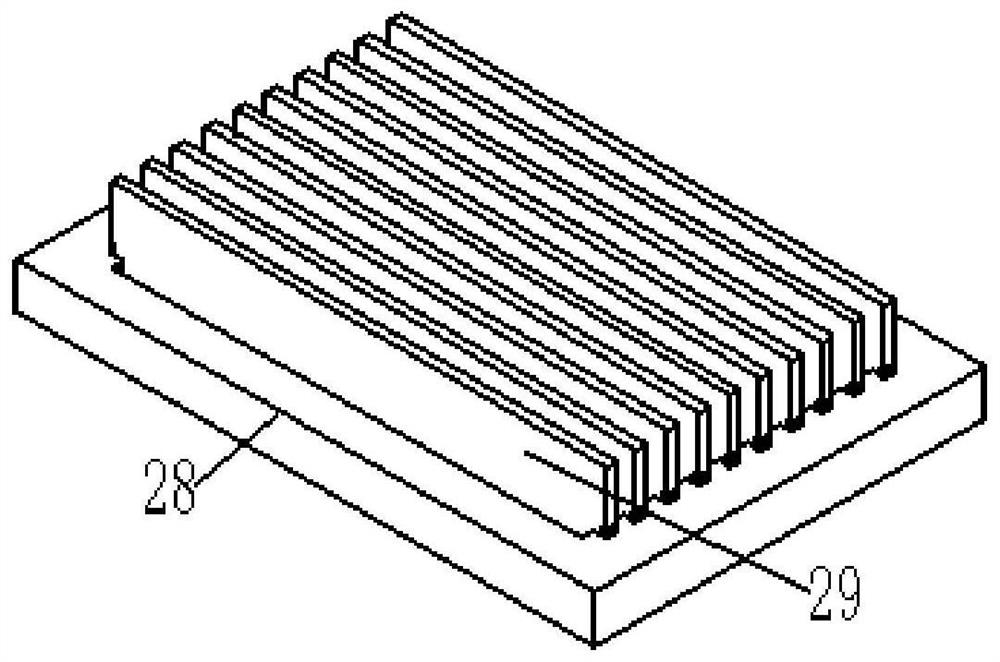
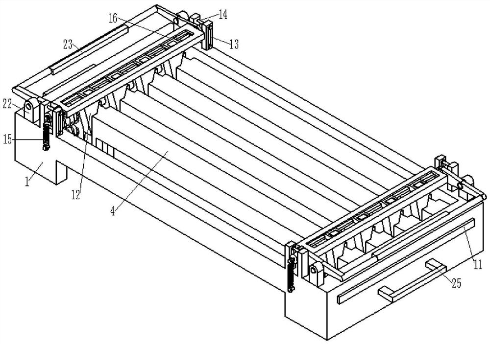
[0039] A device suitable for placing memory sticks in batches in the memory slots of the motherboard, such as image 3 As shown, including the base 1 and the clamp arm 4, the base 1 is the basis of the whole device, and other parts of the device are installed on the base 1. The upper part of the base 1 is a back-shaped structure, and the lower side is provided with a supporting part. When the base 1 is in contact with the material tray 28 or the main board 26, there is a gap between the middle part and the material tray 28 or the main board 26, which is convenient for clamping or placing the memory. strip.

[0040] Figure 8 As shown, the guide rail 2 is installed inside the base 1, and there are two sets of guide rails 2, each group is located on the left and right sides of the base 1, and each set of guide rails 2 includes two parallel to each other, and the guide rail 2 is to provide clips. The arm 4 is a supporting and guiding part that slides left and right. The clamp a...


PUM


Abstract

The invention discloses a device suitable for placing memory banks in a mainboard memory slot in batches, which comprises a base and clamping arms, the resettable clamping arms are mounted on the base, resettable buckles are arranged on one sides of the clamping arms, and a release block for moving the buckle is arranged on one side of the base; a positioning wedge matched with the clamping arms is arranged between the clamping arms, a positioning beam used for moving the positioning wedge is arranged on the upper side of the base, and a pressing handle used for moving the positioning beam is arranged on one side of the base. According to the invention, the spacing of the memory banks is adjusted through the cooperation of the positioning beam and the positioning wedge, so that the device is suitable for trays with different spacing of the memory banks or mainboards with different spacing of memory slots, and is flexible and changeable to use; and by installing different numbers of clamping arms, different numbers of memory banks can be clamped at a time, and the practicability is high. The device is suitable for a server or a PC complete machine needing to be provided with a plurality of memory banks, the memory banks can be held and placed in batches, and the operation that the memory banks are held and placed independently at present is replaced.

Description

technical field [0001] The invention relates to the technical field of memory stick assembly, in particular to a device suitable for placing memory sticks in batches in memory slots of main boards. Background technique [0002] When servers and PCs are produced and assembled, the memory modules are inserted into the memory slots on the motherboard. Such as figure 1 and figure 2 As shown, because the distance between the memory slots on each motherboard is not necessarily equal to the distance between the memory on the tray, the installation process can only transfer the memory sticks from the tray to the memory slots on the motherboard one by one, instead of batching them all at once. Multiple memory sticks are transferred to the motherboard memory slot. [0003] This installation method not only has low production efficiency, but also increases labor costs. When installing server products, sometimes a machine needs to be inserted with 20 or 30 memory sticks. In this ca...

Claims


Application Information

Patent Timeline
Patent Type & Authority Applications(China)
IPC IPC(8): G06F1/18
CPCG06F1/185G06F1/186Y02D10/00
Inventor 许家斌
Owner INSPUR SUZHOU INTELLIGENT TECH CO LTD
Why Eureka
Try Eureka