
Multi-interface test system and method

A test system and interface test technology, applied in error detection/correction, detection of faulty computer hardware, instruments, etc., can solve complex problems, avoid interfering data, solve packet loss, and improve test efficiency.

Pending Publication Date: 2021-11-05
TIANJIN JINHANG COMP TECH RES INST
View PDF0 Cites 2 Cited by
  • Summary
  • Abstract
  • Description
  • Claims
  • Application Information

AI Technical Summary

Problems solved by technology

[0003] Each serial port and IO interface test needs to be equipped with test cables and test computers. When the number of tested interfaces is large, more test cables and test computers are required. , there is no need to conduct a complete physical test on the entire serial port or IO channel. It is only necessary to test whether the serial port controller and the IO controller are working normally to meet the requirements. At this time, the same number of test cables and test computers as the number of interfaces to be tested can be equipped. is too complicated

Method used


Image

  • Multi-interface test system and method
  • Multi-interface test system and method
  • Multi-interface test system and method

Examples


Embodiment 1

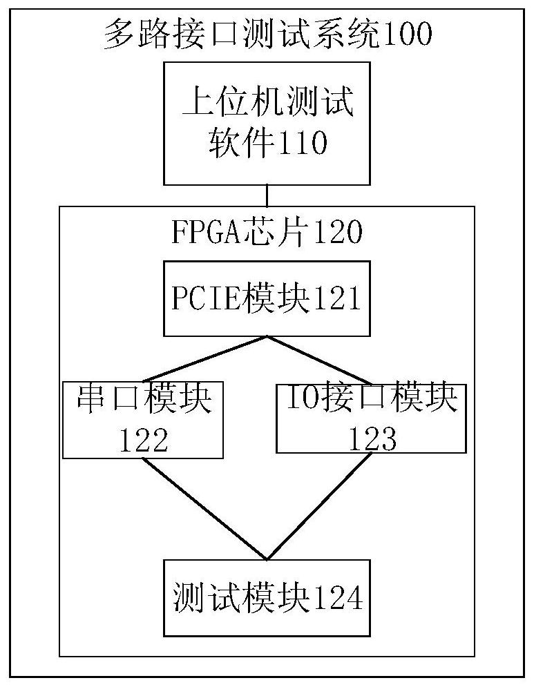
[0035] refer to figure 1 , which shows a schematic structural diagram of a multi-channel interface testing system provided by an embodiment of the present invention, as shown in figure 1 As shown, the multi-channel interface test system 100 can include: a host computer test software 110 and an FPGA chip 120, wherein the FPGA chip 120 can include: a PCIE (peripheral component interconnect express, high-speed serial computer expansion bus standard) module 121, a plurality of Serial port module 122, IO interface module 123 and test module 124, IO interface module 123 can comprise multi-channel IO interface,

[0036] The host computer test software 110 can be connected with the PCIE module 121 in communication, and the PCIE module 121 can be connected with the serial port module 122 and the IO interface module 123 respectively;

[0037] When carrying out the serial port test, the serial port module 122 can be connected with the serial port communication of the computer under test...

Embodiment 2

[0089] refer to Figure 4 , shows a flow chart of the steps of a multi-channel interface testing method provided by an embodiment of the present invention, as Figure 4 As shown, the multi-channel interface testing method may specifically include the following steps:

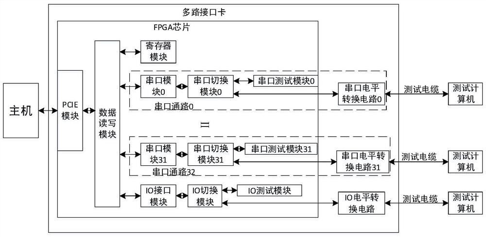
[0090] Step 401: When testing the multi-channel target interface, the host sets the register module to the test mode through the PCIE module, and the serial port switching module connects the corresponding multi-channel serial port module to the serial port test module, and connects the IO interface module to the IO test module.

[0091] The embodiment of the present invention can be applied in the scenario of testing serial ports and / or IO interfaces of multiple computers under test.

[0092] In this embodiment, the target interface may be a serial port and / or an IO interface.

[0093] When testing the multi-channel target interface, the host can set the register module as the test mode through the PCIE modul...


PUM


Abstract

The invention discloses a multi-interface test system and method. The test system comprises upper computer testing software and an FPGA chip, the FPGA chip comprises a PCIE module, a plurality of serial port modules, an IO interface module and a testing module, wherein the IO interface module comprises a plurality of IO interfaces, the upper computer testing software is in communication connection with the PCIE module, and the PCIE module is connected with the serial port modules and the IO interface module. When a serial port test is carried out, the serial port module is in communication connection with a serial port of a tested computer; when the IO interface is tested, the IO interface is connected with the IO interface of the tested computer; and the testing module is configured to test the interface state of the serial port and / or the IO interface of the tested computer. According to the invention, the test efficiency can be improved, the fault elimination efficiency is improved, and test failure caused by interference data is avoided.

Description

technical field [0001] The invention relates to the technical field of computer testing, in particular to a multi-channel interface testing system and method. Background technique [0002] In the field of industrial control, serial ports and IO (Input / Output, input / output) interfaces are commonly used computer communication interfaces, and the implementation methods include dedicated serial ports, IO chip implementations, and FPGA implementations. FPGA implements serial ports and IO ports in a more flexible way, which is convenient for expansion. To perform a serial port test, it is necessary to connect a serial port of the computer under test to the serial port of the test computer, the computer under test and the test computer send and receive data to each other, and judge whether the serial port is working normally by comparing the received data with the sent data. The IO interface test is similar to the serial port test method, which requires the computer under test and...

Claims


Application Information

Patent Timeline
Patent Type & Authority Applications(China)
IPC IPC(8): G06F11/22G06F11/273
CPCG06F11/221G06F11/2733G06F11/2268
Inventor 汤晓磊胡亮
Owner TIANJIN JINHANG COMP TECH RES INST
Learn More