
Drying frame bent pipe lap joint chambering forming machine

A technology for drying racks and forming machines, applied in the directions of feeding devices, positioning devices, storage devices, etc., can solve the problems of high cost, unstable product quality, and heavy repair workload, so as to improve quality and production efficiency, reduce Defect rate and rework workload, the effect of improving connection strength

Pending Publication Date: 2021-11-09
JIANGXI AVONFLOW HVAC TECH CO LTD
View PDF5 Cites 2 Cited by
  • Summary
  • Abstract
  • Description
  • Claims
  • Application Information

AI Technical Summary

Problems solved by technology

[0002] Under the existing technology, during the assembly process of the drying rack, the assembly process of the elbow and the vertical pipe is to insert the elbow into the vertical pipe first, and then connect it by gas shielded welding or resistance welding. However, it is found in production practice that this Both connection methods have defects such as air holes and virtual soldering, which lead to unstable product quality and low yield rate, resulting in heavy workload and high cost for rework

Method used


Image

  • Drying frame bent pipe lap joint chambering forming machine
  • Drying frame bent pipe lap joint chambering forming machine
  • Drying frame bent pipe lap joint chambering forming machine

Examples

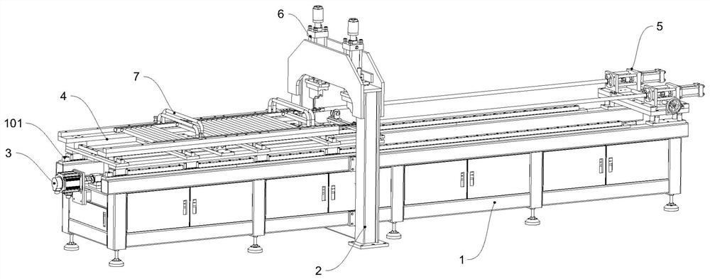
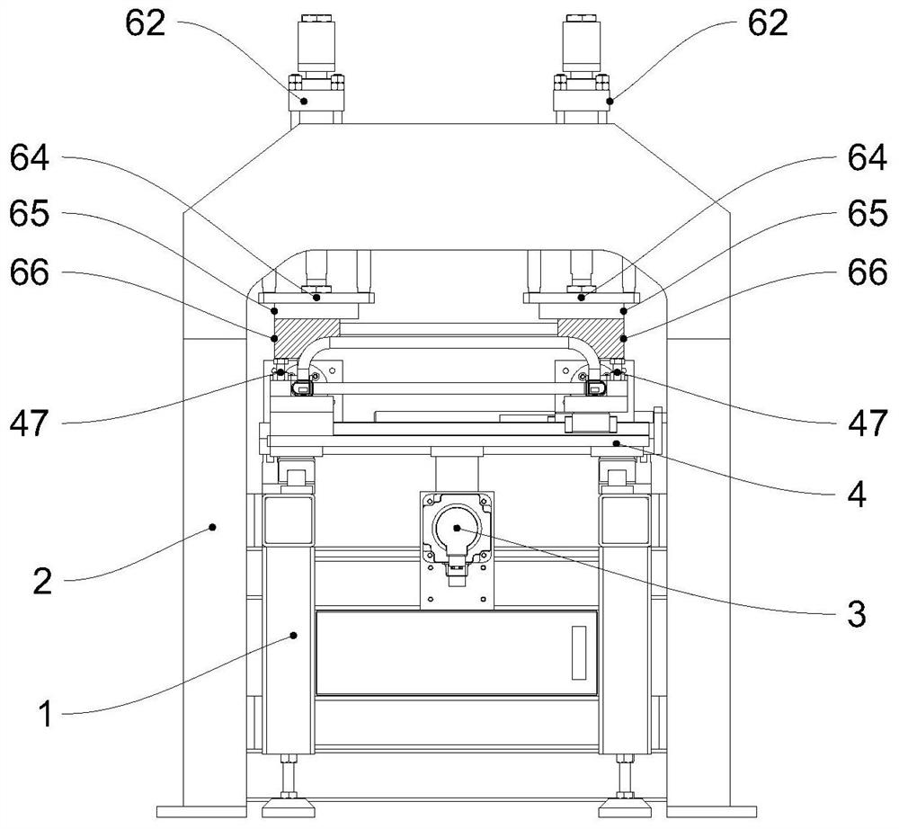
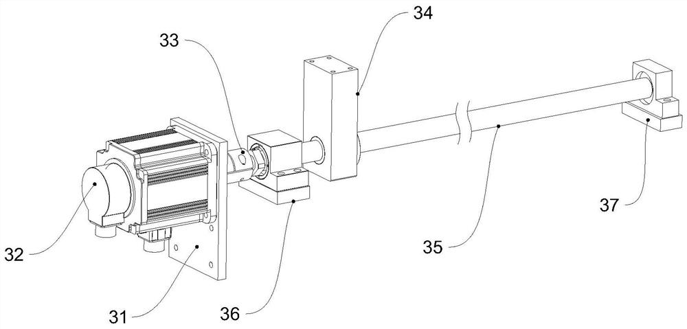

Embodiment Construction

[0024] next combined with Figure 1-7 A specific embodiment of the present invention is described in detail.

[0025] In this embodiment, the direction of the X-axis is taken as the longitudinal direction of the fuselage 1 , that is, the traveling direction of the drying rack 7 to be expanded.

[0026] A drying rack elbow lap expansion forming machine, including a fuselage 1 as a main load-bearing structure, a door frame 2, a feed drive assembly 3, a movable workbench 4, a pipe expansion assembly 5, and a pressure pipe assembly 6, The fuselage 1 is provided with two linear slide rails 101 arranged along the X-axis, the movable table 4 is movably arranged on the slide rails 101, the feed drive assembly 3 is fixed at one end of the fuselage 1, and the output of the feed drive assembly 3 The movable workbench 4 is connected to drive the movable workbench 4 to perform feed movement along the X axis, the drying rack 7 is placed on the movable workbench 4, and the movable workbench...


PUM


Abstract

The invention discloses a drying frame bent pipe lap joint chambering forming machine. The machine comprises a machine body, a portal frame, a feeding driving assembly, a movable workbench, a pipe chambering assembly and a pipe pressing assembly. A linear sliding rail is arranged at the top of the machine body along the X axis; the portal frame is spanned above the machine body; the feeding driving assembly is fixed on one side of the machine body and is used for controlling the moving of the movable workbench; the movable workbench is movably arranged on the sliding rail and connected with the output of the feeding driving assembly, and a drying frame is placed on the movable workbench and is limited in the horizontal plane; the pipe chambering assembly is fixed to one end of the machine body and used for chambering a drying frame bent pipe; and the pipe pressing assembly is arranged on the portal frame, vertically and downwards presses the drying frame and vertically limits the drying frame bent pipe. According to the chambering forming machine, rapid chambering can be conducted on the end portion of the bent pipe inserted into a vertical pipe, the connecting position of the bent pipe and the vertical pipe is firm and tightly attached, the connecting strength of a product and the pressure test qualification rate after brazing are improved, the reject ratio and the repair workload are reduced, and the product quality and the production efficiency are improved.

Description

technical field [0001] The invention relates to the field of hole reaming forming machines, in particular to a drying rack elbow lapping hole reaming forming machine. Background technique [0002] Under the existing technology, during the assembly process of the drying rack, the assembly process of the elbow and the vertical pipe is to insert the elbow into the vertical pipe first, and then connect it by gas shielded welding or resistance welding. However, it is found in production practice that this Both connection methods have defects such as air holes and virtual soldering, which lead to unstable product quality and low yield rate, resulting in heavy workload and high cost for rework. Contents of the invention [0003] According to the problems raised by the background technology, the present invention provides a drying rack elbow lap reaming forming machine to solve the problem. Next, the present invention will be further elaborated. [0004] A drying rack elbow lap e...

Claims


Application Information

Patent Timeline
Patent Type & Authority Applications(China)
IPC IPC(8): B21D39/20B21D43/00B21D7/06
CPCB21D39/20B21D7/06B21D43/006B21D43/003
Inventor 吴剑斌郑辉生
Owner JIANGXI AVONFLOW HVAC TECH CO LTD
Learn More