
Grinding equipment for steam turbine steel casting production

A technology for steel castings and steam turbines, which is applied in the production field of steam turbine steel castings, can solve the problems of low scope of application, difficult to control force, uneven force, etc., and achieve the effects of improving environmental protection, easy adjustment and fixation, and improved flexibility.

Inactive Publication Date: 2021-11-09
WENZHOU KAICHENG MACHINERY
View PDF8 Cites 3 Cited by
  • Summary
  • Abstract
  • Description
  • Claims
  • Application Information

AI Technical Summary

Problems solved by technology

[0004] The purpose of the present invention is to provide a grinding equipment for the production of steel castings based on steam turbines, so as to solve the problem that it is difficult to control the grinding force of the steel castings proposed in the above background technology, and the grinding force is too large to cause damage to the grinder and the steel castings. If the force is too small, the grinding efficiency is too slow, the force is uneven, and the processing quality is poor. It cannot be adjusted according to the size and specification of the steel casting. The waste of resources can only be used for fixed grinding of steel castings of a specific length, which has a low scope of application and is not convenient for grinding the ends of steel castings. It is not possible to use a flexible displacement grinder, and it is easy to miss dead angles. The dust raised by grinding and iron filings will pollute the surrounding environment, and the problem of centralized collection and treatment cannot be achieved.

Method used


Image

  • Grinding equipment for steam turbine steel casting production
  • Grinding equipment for steam turbine steel casting production
  • Grinding equipment for steam turbine steel casting production

Examples


Embodiment Construction

[0028] The following will clearly and completely describe the technical solutions in the embodiments of the present invention with reference to the accompanying drawings in the embodiments of the present invention. Obviously, the described embodiments are only some, not all, embodiments of the present invention. Based on the embodiments of the present invention, all other embodiments obtained by persons of ordinary skill in the art without making creative efforts belong to the protection scope of the present invention.

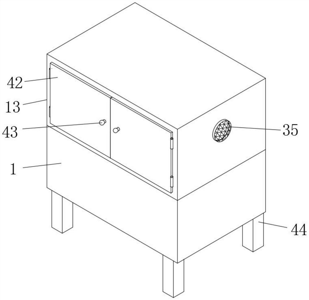
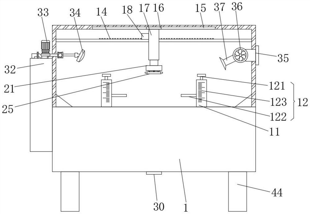
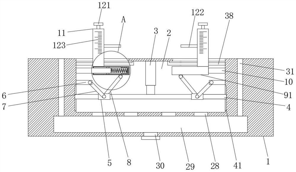
[0029] Such as Figure 1-4As shown, the present invention provides a technical solution: a kind of grinding equipment based on the production of steam turbine steel castings, including an operation cabinet 1, the inside of the operation cabinet 1 is provided with a tank body 2, and the top of the tank body 2 is bolted with a first Cylinder 3, the lower end of the first cylinder 3 is bolted with elevating rod 4, both sides of the surface of elevating rod 4 are ...


PUM


Abstract

The invention discloses grinding equipment for steam turbine steel casting production. According to the grinding equipment, a steel casting is placed on the top of an operation cabinet, and a first cylinder is started to drive a lifting rod to vertically move in a lifting groove; a movable frame is slide on the surface of the lifting rod, and therefore a push rod is driven to extrude an elastic mechanism; a clamping pipe is driven by the elastic mechanism to move on the surface of an L-shaped pipe, and therefore the steel casting is fixedly clamped in the horizontal direction; a hold-down mechanism is used for fixing the steel casting in the vertical direction, and therefore adjustment and fixation are facilitated; and the flexibility is improved. According to the grinding equipment, a first motor is started to drive a gear to move on the top of a toothed bar, and a second cylinder is adjusted to drive a shell to move downwards; a second motor is started to drive a grinding wheel to rotate, and therefore the steel casting is ground; in the pressing process, a supporting spring is compressed, and a water pump is started to enable water in a water tank to spray out from a sprinkler head; and thus, the situation that dust and scrap iron raised during grinding pollutes the surrounding environment is avoided, and the environmental protection effect is improved.

Description

technical field [0001] The invention relates to the technical field of production of steel castings for steam turbines, in particular to grinding equipment for the production of steel castings based on steam turbines. Background technique [0002] The steam turbine, also known as the steam turbine engine, is a rotary steam power device. The high-temperature and high-pressure steam passes through the fixed nozzle to become an accelerated air flow and then sprays onto the blades, so that the rotor equipped with blade rows rotates and works externally. A steam turbine is a rotating machine powered by steam and converts the thermal energy of the steam into mechanical work. It is the most widely used prime mover in modern thermal power plants. The steam turbine has the advantages of large power, high efficiency, and long life. Due to the continuous development of metallurgical technology, the structure of the steam turbine has also been greatly improved. Large units generally ad...

Claims


Application Information

Patent Timeline
Patent Type & Authority Applications(China)
IPC IPC(8): B24B9/04B24B41/06B24B47/00B24B47/12B24B47/14B24B47/16B24B55/06
CPCB24B9/04B24B41/06B24B47/00B24B47/14B24B47/16B24B47/12B24B55/06
Inventor 许秋林黄晓贵陈益武厉李楚李奕澄
Owner WENZHOU KAICHENG MACHINERY
Learn More