

Novel tunneling method and device
A technology of tunneling and in-device, applied in tunnels, mining devices, earth-moving drilling, etc., can solve the problems of increasing energy consumption of tunnel construction, strong integrity of shield equipment, complex structure of shield equipment, etc., so as to reduce carbon emissions. And the effect of construction cost, flexible construction method and strong engineering application value
- Summary
- Abstract
- Description
- Claims
- Application Information
AI Technical Summary
Problems solved by technology
Method used
Image

Examples
Embodiment Construction
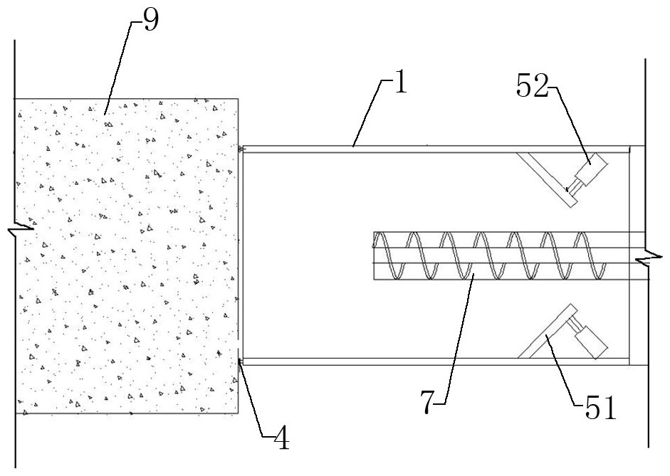
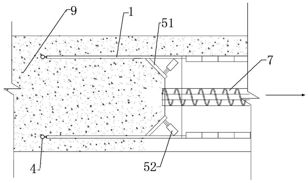
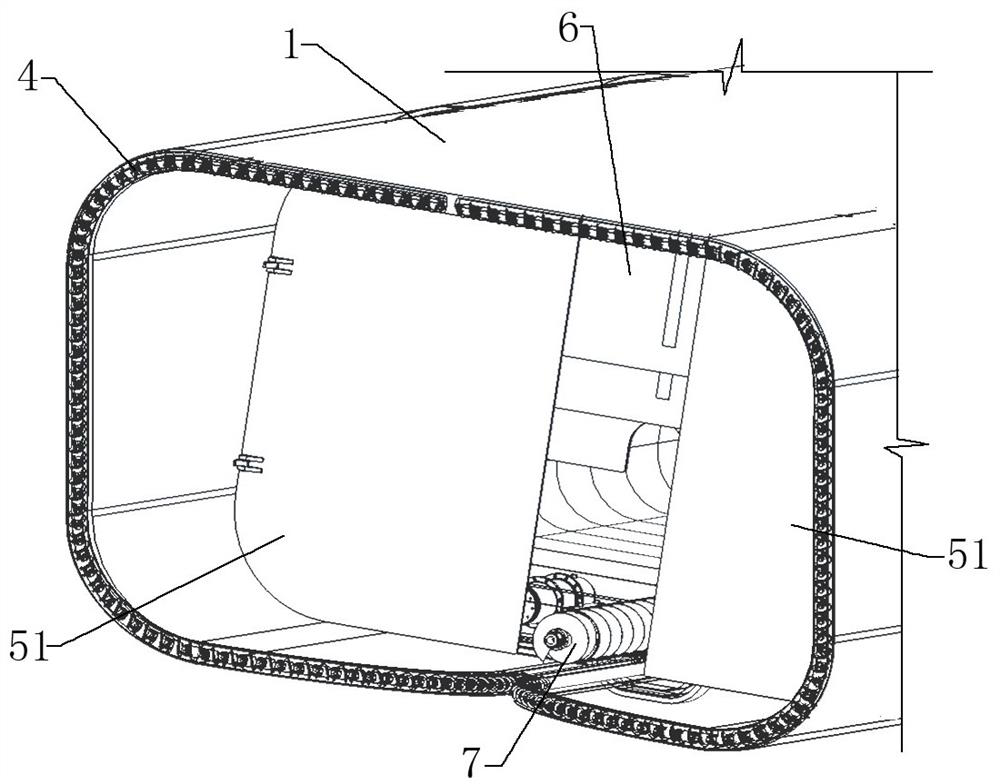
[0041] Such as Figure 1 to Figure 7 As shown, a new tunnel excavation method of the present invention uses the frame-shaped drilling tool 4 located at the front end of the cylindrical excavation device to cut and excavate along the outer periphery of the tunnel face 9, and at the same time adjust the excavation of the soil cut into the excavation device. To realize tunnel excavation. The soil cut into the tunneling device is on the rear end side of the tunneling direction, and the axial stress is applied forward by the stress applying device to form a soil plug that promotes the stability of the face 9; while tunneling, the rear end of the soil plug is exposed. unearthed. Specifically include the following steps:
[0042] Step 1. Site preparation;
[0043] In this step, in addition to hardening the site and ensuring that the relevant hard conditions of the site meet the construction requirements, a reasonable equipment installation plan should be formulated according to th...
PUM
 Abstract
Description
Claims
Application Information