
Mounting method of visual plug template group device of template trolley plug

A technology of plug formwork and formwork trolley, which is applied in shaft equipment, earthwork drilling, wellbore lining, etc. It can solve problems such as uneven pressure, incomplete concrete pouring, and easy occurrence of voids or air bubbles, so as to reduce voids or air bubbles , Accelerate the construction progress, improve the effect of construction quality

Pending Publication Date: 2021-11-09
LUOYANG GAOFEI BRIDGE MACHINERY CO LTD
View PDF0 Cites 0 Cited by
  • Summary
  • Abstract
  • Description
  • Claims
  • Application Information

AI Technical Summary

Problems solved by technology

[0002] At present, the two ends of the formwork trolley formwork for pouring concrete in tunnels need to be sealed by plug formwork before construction. Most of the existing formwork plugs are steel formwork plugs. The gap between the tunnel arch walls is sealed with rubber strips; because the gap between the tunnel arch walls and the steel plug formwork is inconsistent, the rubber strips inserted in the gap are of the same thickness for padding, and the rubber strips are different from the gap. Matching, the uneven pressure of the rubber strip through the steel plug formwork affects the sealing of the formwork plug; in addition, during the construction process, the pouring port is located in the middle of the formwork, and the steel plug formwork cannot be judged because the steel formwork is opaque. The construction state of the inner concrete pouring, the concrete pouring on the inner side of the steel plug formwork is not full, and cavities or air bubbles are prone to appear, which need to be repaired manually, which cannot meet the construction requirements and affect the construction quality of the tunnel donor lining; in view of the above reasons, A method for installing the visual plug template group device for the template trolley plug is now proposed

Method used


Image

  • Mounting method of visual plug template group device of template trolley plug
  • Mounting method of visual plug template group device of template trolley plug
  • Mounting method of visual plug template group device of template trolley plug

Examples


Embodiment 1

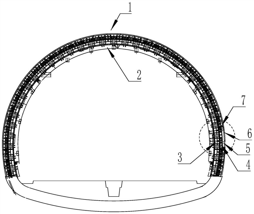
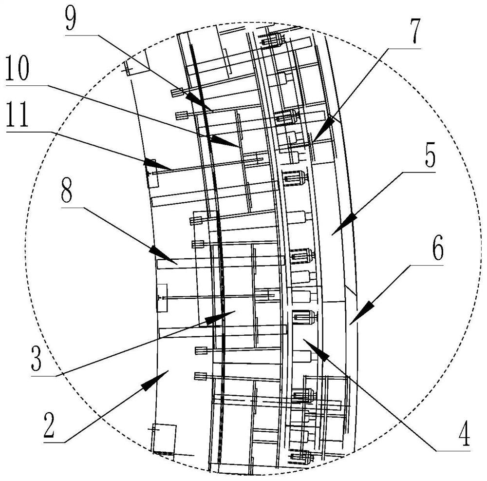
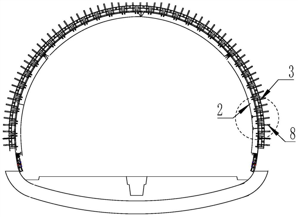
[0032] The top and both sides of formwork trolley 1 are set as arched formwork 2-1, the inner sides of both ends of formwork 2-1 are respectively set as formwork flanges 2, and the outer sides of formwork flanges 2 are respectively set as three sets of plug steel Formwork 3; three sets of plugging steel formwork 3 on the outside of formwork flange 2 are combined to form an arched plugging steel formwork, and the outer sides of the arched plugging steel formwork are respectively set as four-layer telescopic plugging molds. The molds are arranged in turn from the inside to the outside as a buried waterstop 14, a telescopic plug template 4, a plug heightening module 5, and an elastic pad 6. The upper end of the elastic pad 6 corresponds to the arch wall waterstop 13 on the inner wall of the tunnel;

[0033] A pair of steel mold turning frames 9 are arranged between the outer sides of the formwork flange 2 and the plug steel formwork 3 respectively, and Joule 2-2 is set between the...

Embodiment 2

[0040] When the gap between the outside of the first piece of plug steel formwork 3 at one end of formwork trolley 1 and the inner wall of the tunnel is sealed, the telescopic plug formwork 4, the plug heightening module 5, and the elastic cushion block 6 correspond to the plug steel formwork respectively. 3. After the outer edge is manually corrected, the telescopic screw 4-3 is manually rotated, and the telescopic screw 4-3 pushes the telescopic module 4-1, the plug heightening module 5, and the elastic pad 6 to run outwards and the tunnel After the inner wall is contacted, extruded and sealed, the rotation of the telescopic lead screw 4-3 is stopped, and the sealing of the gap outside the first plug steel template 3 is completed.

Embodiment 3

[0042] After the gap sealing between the plug steel formwork 3 and the inner wall of the tunnel is completed, the plug support frame 7 is placed on the outside of the telescopic plug formwork 4 and the plug heightening module 5, and a pair of columns at the outer ends of the double-layer steel form bracket 10 After the frame support post 8 is manually inserted upwards to the outside of the plug support frame 7, a pair of post screw 12 is manually rotated and fixed to a pair of frame support post 8 respectively, and the first plug is completed. Sealing of the gap between the outside of the steel formwork 3 and the inner wall of the tunnel;

[0043] According to the above operation method, install each piece of plugging steel formwork 3 from one end to the other end of the formwork trolley 1 to the other end to seal the gap between the outside of the tunnel inner wall until all the ends of the formwork trolley 1 are plugged outside the steel formwork 3 After the gap sealing with...


PUM


Abstract

The invention relates to a mounting method of a visual plug template group device of a template trolley plug. According to the method, three groups of plug steel templates of a template trolley are respectively turned upwards by 90 degrees through a steel template turnover frame to form an arch shape, a middle-buried water stop belt is manually laid on the arch plug steel template, gaps between the upper surface of the middle-buried water stop belt on the outer side of the plug steel templates from one end of the template trolley to the other end of the template trolley and the inner wall of the tunnel is plugged in sequence, a telescopic plug template, a plug heightening module and an elastic cushion block are manually and sequentially installed on the outer side of the plug steel template in a blocking and layering mode, and a telescopic lead screw is manually rotated to push a telescopic module, a plug heightening module and an elastic cushion block to move outwards to make contact with the inner wall of the tunnel, and extrusion sealing is achieved. According to the mounting method, the plugging width between the telescopic plug template and the telescopic module is adjusted through the telescopic lead screw, the sealing effect can be improved, the construction state can be observed through the perspective rear plug template of the plug heightening module, and the construction quality of tunnel lining is improved.

Description

technical field [0001] The invention relates to the installation of a plug template of a template trolley, in particular to a method for installing a visual plug template group device for a plug of a template trolley. Background technique [0002] At present, the two ends of the formwork trolley formwork for pouring concrete in tunnels need to be sealed by plug formwork before construction. Most of the existing formwork plugs are steel formwork plugs. The gap between the tunnel arch walls is sealed with rubber strips; because the gap between the tunnel arch walls and the steel plug formwork is inconsistent, the rubber strips inserted in the gap are of the same thickness, and the rubber strips are different from the gap. Matching, the uneven pressure of the rubber strip through the steel plug formwork affects the sealing of the formwork plug; in addition, during the construction process, the pouring port is located in the middle of the formwork, and the steel plug formwork ca...

Claims


Application Information

Patent Timeline
IPC IPC(8): E21D11/10
CPCE21D11/102
Inventor 黄高飞程朝亮
Owner LUOYANG GAOFEI BRIDGE MACHINERY CO LTD
Learn More