


Quick Research
Generate reliable direction feasibility study reports for your R&D in just a few steps.

Technical Q&A
Discover and master advanced knowledge NOW. Basics, ideas, possibilities, all at once.

Find Solutions
As an expert in R&D theories, this can generate solutions to your technical problems instantly.

Evaluate Feasibility
Analyze your overall solution with one click, know your potential R&D risks in advance.

Monitor Landscape
Get weekly tech updates, stay abreast of the latest tech innovations and key insights.
Fin structure, heat exchange tube and falling film evaporator
A technology of heat exchange tubes and fins is applied in the field of heat exchangers, which can solve the problems of unsatisfactory heat transfer efficiency of falling film evaporators, and achieve the effect of enhancing performance and enhancing heat transfer efficiency.
- Summary
- Abstract
- Description
- Claims
- Application Information
AI Technical Summary
Problems solved by technology
Method used
Image

Examples
Embodiment 1
[0034] The invention provides a fin structure, including an evaporation chamber, a transient heat conduction enhancement structure and a flow channel, the evaporation chamber is formed between the top and the bottom of the fin, the flow channel communicates with the evaporation chamber, and the transient heat conduction enhancement structure is formed At the bottom of the fins, the transient heat conduction of the heat exchange tube can be enhanced.
[0035] When the fin structure is set on the outer surface of the heat exchange tube, the transient heat conduction will occur in the area where the transient heat conduction strengthening structure is in contact with the heat exchange tube, which enhances the heat transfer efficiency of the transient heat conduction process, thus enhancing the heat transfer efficiency. Performance of heat pipes and falling film evaporators.
[0036] Specifically, such as Figure 1-Figure 4 As shown, the transient heat conduction enhancing struct...
Embodiment 2
[0045] Such as Figure 1-Figure 5 As shown, the present invention also provides a heat exchange tube, which includes a tube body and any one of the above fin structures, and the fin structure is formed on the outer surface of the tube body.
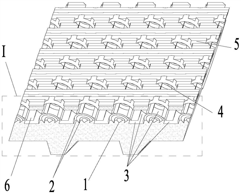
[0046] As an optional implementation, such as figure 1 and Figure 5 As shown, the top of the fin is provided with a fin cap, and the fin cap is provided with an axial stripe rib 5 . The axial stripes on the wing top cover increase the axial surface tension and elongate the liquid film, thereby strengthening the axial film distribution.
[0047] As an optional embodiment, the bubble escape port 4 of the evaporation chamber is formed on the fin top cover. The finned top cover can trap a small amount of gas, leaving a gasification core in the evaporation chamber after the bubbles leave, reducing the time for the next bubble growth.
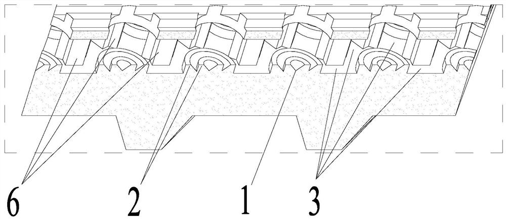
Embodiment 3
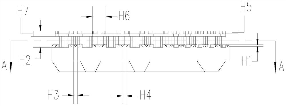
[0049] The specific embodiment of the present invention provides a falling film heat exchange tube, which includes a tube body and a fin structure on the outside of the tube body, and the root of the fin is connected with the tube body as a whole. Such as figure 1As shown, the falling film heat exchange tube fin includes a gasification core generation area 1 , annular shallow ribs 2 , intersecting flow channels 3 , bubble escape ports 4 in the evaporation chamber, and axial stripe ribs 5 . Wherein, the base of the fins is composed of closely arranged hexagons, and each hexagon is an independent evaporation chamber. The middle section of each side of the hexagon has a flow channel, so that the flow channel becomes a staggered flow channel 3 . Each hexagon has a gasification core area in the center, which is conical in shape, with a depth of H1 and a diameter of H3. With the apex of the gasification core area as the center, annular shallow ribs 2 are arranged to enhance transi...
PUM
| Property | Measurement | Unit |
|---|---|---|
| Height | aaaaa | aaaaa |
| Depth | aaaaa | aaaaa |
| Width | aaaaa | aaaaa |
Abstract
Description
Claims
Application Information
 - R&D Engineer
- R&D Manager
- IP Professional
- Industry Leading Data Capabilities
- Powerful AI technology
- Patent DNA Extraction
Browse by: Latest US Patents, China's latest patents, Technical Efficacy Thesaurus, Application Domain, Technology Topic, Popular Technical Reports.
© 2024 PatSnap. All rights reserved.Legal|Privacy policy|Modern Slavery Act Transparency Statement|Sitemap|About US| Contact US: help@patsnap.com