
Two-way ventilation structure and oxygen supply device capable of adjusting concentration of inhaled oxygen

A ventilation structure and oxygen supply technology, applied in the field of medical devices, can solve problems such as unfavorable industrial mass production, difficult to grasp the accuracy of adjustment, and inability to standardize interfaces, so as to improve the effect of ventilation and oxygen supply, expand the scope of clinical application, reduce The effect of dead space

Pending Publication Date: 2021-11-12
BEIJING MINGDASHU MEDICAL TECH CO LTD
View PDF1 Cites 1 Cited by
  • Summary
  • Abstract
  • Description
  • Claims
  • Application Information

AI Technical Summary

Problems solved by technology

[0003] A patent document whose publication number is CN111135413A discloses a kind of airtight oxygen inhaler, which is provided with an air storage bag and a mouth and nose mask, and the proportion of the external air mixed by the proportional control valve comprising a valve and a baffle adjustment, but this technical solution still has certain deficiencies in actual use:
[0004] 1. On the same cross-section perpendicular to the pipeline, a two-way air valve is installed at the same time. In order to meet the oxygen inhalation requirements of the human body, the diameter of the pipeline will be larger and the pipeline will be thicker, so it cannot be connected to the external medical field. standard interface;
[0005] 2. It is not practical to adjust the oxygen intake and air intake at the same time by rotating the valve baffle. This method is not only difficult to grasp the accuracy of adjustment, but also increases the amount of operation for medical staff and is prone to mistakes;
[0006] 3. This rotary valve baffle structure is relatively complicated to manufacture, which is not conducive to large-scale industrial production;

Method used


Image

  • Two-way ventilation structure and oxygen supply device capable of adjusting concentration of inhaled oxygen
  • Two-way ventilation structure and oxygen supply device capable of adjusting concentration of inhaled oxygen
  • Two-way ventilation structure and oxygen supply device capable of adjusting concentration of inhaled oxygen

Examples


Embodiment 1

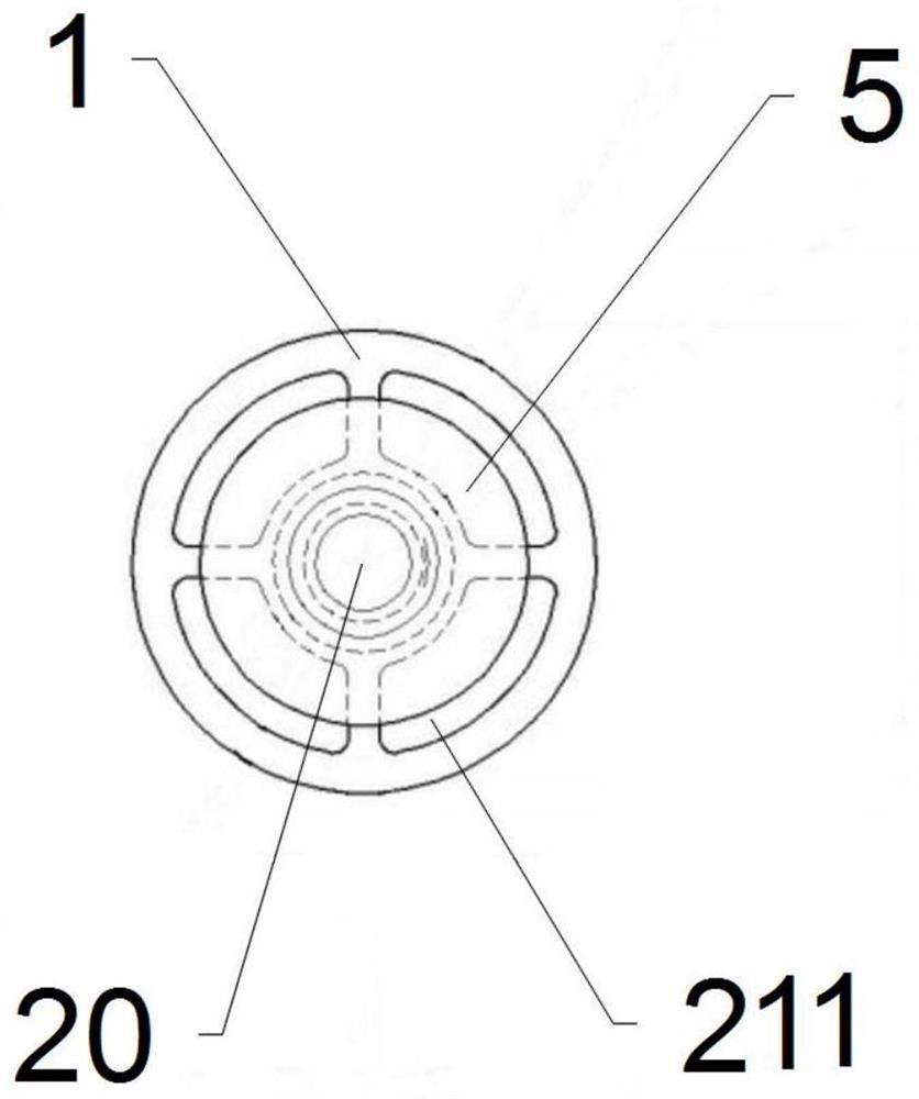
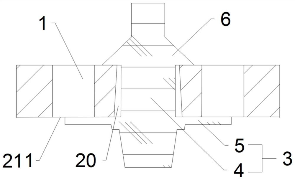
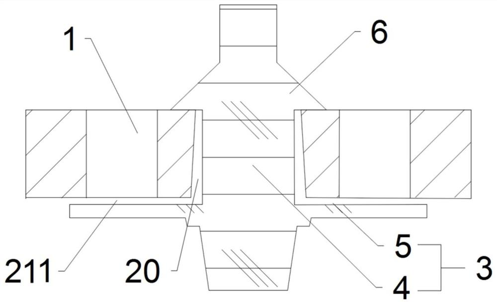
[0040] Such as figure 1 and figure 2 As shown, the present invention proposes a two-way ventilation structure, including a ventilation valve mechanism. The ventilation valve mechanism is arranged on the pipe wall of the ventilation pipeline. The ventilation valve mechanism can maintain the ability of gas convection between the inside and outside of the ventilation pipeline, and when the pressure inside the ventilation pipeline is greater than the external pressure, the airflow path from the ventilation pipeline to the outside will be expanded, so that the inside of the ventilation pipeline The airflow can quickly escape to the outside.

[0041] In the present invention, the ventilation valve mechanism includes a first air hole 1, a convection passage, and a valve body 3 installed in the first air hole 1, wherein the valve body 3 can be opened to the outside when the internal pressure of the ventilation pipeline is greater than the external pressure , so that the gas inside ...

Embodiment 2

[0049] Such as Figure 5 As shown, the difference from the above-mentioned embodiment is that in this embodiment, the convection channel includes a convection hole 212, and the convection hole 212 is directly arranged on the ventilation pipeline. At this time, in some examples, the ventilation valve plate 5 can completely block the ventilation part of the first air hole 1, only when the pressure in the ventilation pipeline is greater than the external pressure, the first air hole 1 has the ventilation ability after the ventilation valve piece 5 is opened, and when the ventilation valve piece 5 is not opened, The ventilation pipeline conducts two-way gas convection inside and outside through the convection hole 212 directly opened on the pipe wall; in addition, in some examples, the ventilation valve plate 5 can still leave a gap 211 between the ventilation part of the first air hole 1, that is, at the same time The gap 211 and the convection hole 212 serve as a convection pass...

Embodiment 3

[0052] In some examples, such as Figure 6 As shown, a regulating valve plate 7 is installed at the convection hole 212. The regulating valve plate 7 can completely cover the convection hole 212 to prevent gas from entering and exiting the convecting hole 212. When the user rotates the regulating valve plate 7, the regulating valve can be changed. The sheet 7 covers the area of ​​the convection hole 212 so as to adjust the ventilation capacity of the convection hole 212 .


PUM


Abstract

The invention relates to a two-way ventilation structure and an oxygen supply device containing the two-way ventilation structure and capable of adjusting the concentration of inhaled oxygen. The two-way ventilation structure comprises a ventilation valve mechanism; and the ventilation valve mechanism is arranged on the pipe wall of a ventilation pipeline and used for keeping two-way air circulation inside and outside the ventilation pipeline and expanding an air flow channel flowing from the ventilation pipeline to the outside when the internal pressure of the ventilation pipeline is larger than the external pressure. The oxygen supply device with the two-way ventilation structure is provided with an inspiration pipeline and an expiration pipeline; an inspiration valve plate and an expiration valve plate are responsible for air circulation of inspiration and expiration respectively; the concentration of inspired oxygen is adjusted by adjusting a convection channel of the two-way ventilation structure on the pipe wall of the expiration pipeline; the principle is simpler and more reasonable; therefore, the pipeline is more compact; the dead space amount is reduced; the ventilation and oxygen supply effects are improved; and meanwhile, the oxygen supply device can be connected with various oxygen supply devices with standard connectors, such as masks and nasal masks, is wider in applicability, and can adjust the oxygen concentration of inhaled air oxygen to be in a reasonable range according to clinical requirements.

Description

technical field [0001] The invention belongs to the technical field of medical devices, in particular to a two-way ventilation structure and an oxygen supply device with the structure which can adjust the concentration of inhaled oxygen. Background technique [0002] Hypoxemia refers to the lack of oxygen in the blood, mainly manifested as a decrease in arterial oxygen partial pressure (PaO2) and pulse oxygen saturation (SpO2), usually due to airway obstruction, respiratory depression, lung disease, etc. Oxygen supply is an effective means to prevent its occurrence. Nowadays, painless technology is widely used in clinical practice. Due to its good sedation and analgesia, it improves the completion rate and accuracy of diagnosis and treatment, and meets people’s needs for comfortable medical care. It has been accepted by most examinees and medical workers. The most common painless technique in the endoscopy room or day operating room is deep sedation and general anesthesia w...

Claims


Application Information

Patent Timeline
Patent Type & Authority Applications(China)
IPC IPC(8): A61M16/00A61M16/06A61M16/10A61M16/20
CPCA61M16/00A61M16/204A61M16/205A61M16/06A61M16/022A61M16/1005A61M2016/1025
Inventor 田鸣白俠路丁滔
Owner BEIJING MINGDASHU MEDICAL TECH CO LTD
Learn More