A single-power multi-die stamping machine
A multi-mold and stamping machine technology, applied in the field of stamping equipment, can solve the problems of difficult positioning and introduction of deformed workpieces, inconvenient automatic switching of workpieces to be stamped, etc., and achieve the effect of ensuring continuity
- Summary
- Abstract
- Description
- Claims
- Application Information
AI Technical Summary
Problems solved by technology
Method used
Image
Examples
Embodiment 1
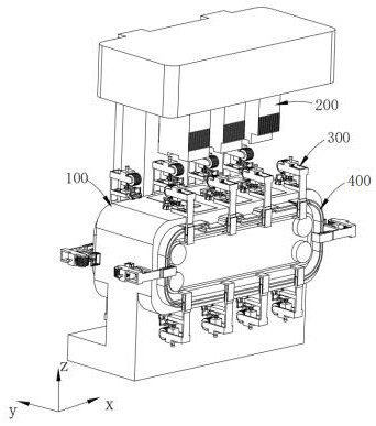
[0036] like figure 1 As shown, a single-power multi-die stamping machine includes:
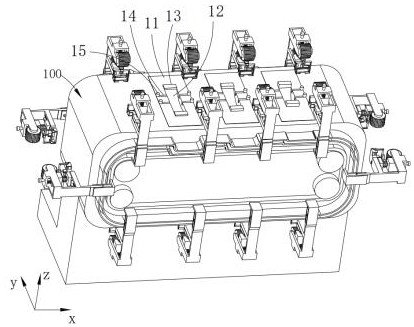
[0037] stamping table 100;
[0038] A stamping assembly 200, the stamping assembly 200 is arranged above the stamping table 100;
[0039] holding parts 300 arranged on both sides of the punching table 100; and
[0040] a driving part 400, the power end of the driving part 400 is connected to the holding part 300;
[0041]The driving part 400 drives the workpiece clamped by the holding part 300 to perform continuous stamping positioning on the stamping table 100. The holding part 300 loosens and positions the workpiece when the stamping assembly 200 is stamping, and continues to lock the workpiece after stamping is completed.
[0042] It is not difficult to see from the above content that during the stamping process of the workpiece (for example, a sheet-shaped strip-shaped workpiece is stamped into a U-shaped shape), the two ends of the workpiece are clamped by the holding part 300, and the...
Embodiment 2
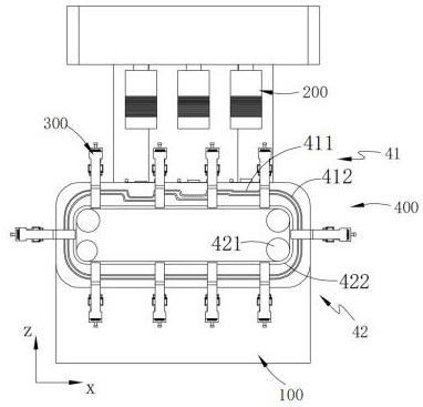
[0080] like figure 2 and 6 As shown, the components that are the same as or corresponding to those in the first embodiment are marked with the corresponding reference numerals in the first embodiment. For the sake of simplicity, only the differences from the first embodiment will be described below. The difference between the second embodiment and the first embodiment is that the driving unit 400 includes:
[0081] guide rail 41;
[0082] Drive track 42, described drive track 42 is arranged on the inner side of described guide track 41; And
[0083] an adjustment assembly 43, the adjustment assembly 43 is connected to the holding part 300;
[0084] While the driving rail 42 drives the adjusting assembly 43 to move on the punching table 100 together with the holding part 300 , the adjusting assembly 43 follows the guiding direction of the guiding rail 41 to adjust the punching height.
[0085] In this embodiment, when the driving part 400 drives the holding part 300 to per...
PUM
 Abstract
Description
Claims
Application Information
 - R&D
- Intellectual Property
- Life Sciences
- Materials
- Tech Scout
- Unparalleled Data Quality
- Higher Quality Content
- 60% Fewer Hallucinations
Browse by: Latest US Patents, China's latest patents, Technical Efficacy Thesaurus, Application Domain, Technology Topic, Popular Technical Reports.
© 2025 PatSnap. All rights reserved.Legal|Privacy policy|Modern Slavery Act Transparency Statement|Sitemap|About US| Contact US: help@patsnap.com


