Rapid drying device for garment printing and dyeing

A technology of rapid drying and drying device, which is applied in the processing of textile materials, the configuration of equipment for processing textile materials, and the removal of liquid/gas/vapor with squeeze rollers, which can solve the problems of high time consumption, low drying efficiency of the device, Problems such as slow drying speed to avoid curling

Inactive Publication Date: 2021-11-12
张昕
View PDF0 Cites 0 Cited by
  • Summary
  • Abstract
  • Description
  • Claims
  • Application Information

AI Technical Summary

Problems solved by technology

[0002] Clothing refers to the general term for clothing that decorates the human body. In the process of clothing production and processing, the cloth needs to be dehydrated and dried to make the cloth dry and easy to operate in the next step. When the cloth is dried, the cloth needs to be dried quickly to improve Work efficiency, in the process of drying the cloth in the existing drying device, only one side of the cloth can be dried, so that the drying speed is slow, and in the drying process, the silk scarf is prone to wrinkles Due to the situation, the moisture inside the silk scarf fabric cannot be evaporated quickly, and it takes a lot of time, which leads to the low drying efficiency of the device. Before the fabric enters the drying device, the existing equipment cannot quickly remove the excess water in the fabric. Extrusion will affect the later drying. In addition, the existing equipment can only be heated and dried alone, and the drying efficiency is low.

Method used


Image

  • Rapid drying device for garment printing and dyeing
  • Rapid drying device for garment printing and dyeing
  • Rapid drying device for garment printing and dyeing

Examples


Embodiment approach

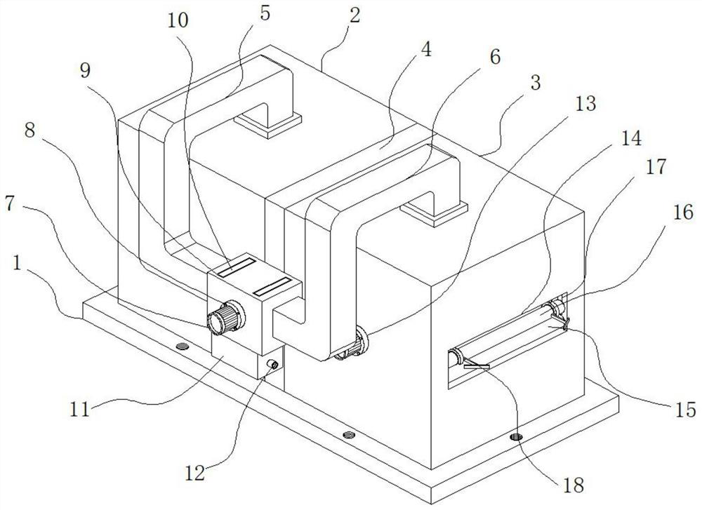
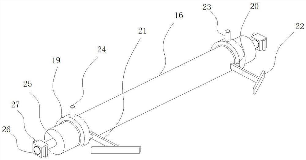
[0027] As a preferred embodiment of the present invention, the anti-rolling device 18 includes an arc frame 19, a rotating rod 20 is installed on one side of the inner wall of the arc frame 19, and a support rod 21 is installed on the rotating rod 20, One end of the support rod 21 is welded with a slant plate 22 , the two ends of the upper roll 16 are fixed with mounting columns 25 , and the two ends of the mounting column 25 are equipped with sliders 26 .

[0028] As a preferred embodiment of the present invention, the mounting column 25 is installed inside the chute 17 through the slider 26, the two sides of the slider 26 are welded with limit blocks 27, and the inner wall of the chute 17 has a There is a limit slot, and the limit block 27 is installed inside the limit slot.

[0029] As a preferred embodiment of the present invention, the top of the arc-shaped frame 19 is welded with a support column 23, the inside of the support column 23 has a cavity, the inside of the cav...


PUM


Abstract

The invention provides a quick drying device for garment printing and dyeing. The drying device comprises a drying device body; the drying device body comprises a base; a cooling box and a heating box are fixed at the top of the base; a partition plate is mounted between the cooling box and the heating box; an air inlet pipe is mounted at the top of the cooling box; and an exhaust pipe is mounted at the top of the heating box. When the rapid drying device for garment printing and dyeing is used, heat generated by a heating plate is blown to cloth from the upper end and the lower end through a motor, so that the cloth is bidirectionally and rapidly heated, dried and used; and steam is generated after the internal cloth is heated, the steam enters the exhaust pipe along with high-temperature air, the steam moves towards a filter box under the driving of fan blades, the internal steam is adsorbed through a moisture absorption plate in the filter box, the adsorbed air is cooled, the cooled air enters the cooling box through the air inlet pipe, and the cold air is blown to the heated cloth, so that the cloth is rapidly dried and used conveniently through alternate cooling and heating.

Description

technical field [0001] The invention relates to the field of clothing printing and dyeing equipment, in particular to a fast drying device for clothing printing and dyeing. Background technique [0002] Clothing refers to the general term for clothing that decorates the human body. In the process of clothing production and processing, the cloth needs to be dehydrated and dried to make the cloth dry and easy to operate in the next step. When the cloth is dried, the cloth needs to be dried quickly to improve Work efficiency, in the process of drying the cloth in the existing drying device, only one side of the cloth can be dried, so that the drying speed is slow, and in the drying process, the silk scarf is prone to wrinkles Due to the situation, the moisture inside the silk scarf fabric cannot be evaporated quickly, and it takes a lot of time, which leads to the low drying efficiency of the device. Before the fabric enters the drying device, the existing equipment cannot quic...

Claims


Application Information

Patent Timeline
Patent Type & Authority Applications(China)
IPC IPC(8): D06B15/09D06B23/22D06B23/20D06B15/02D06B23/02B01D53/26D06C15/08
CPCD06B15/09D06B23/22D06B23/20D06B15/02D06B23/028B01D53/26D06C15/08
Inventor 张昕
Owner 张昕
Why Eureka
Try Eureka