Sewage marine disposal and discharge device
A technology for marine disposal and discharge devices, applied in water supply devices, valve devices, water conservancy projects, etc., can solve the problems of high pollution level, inability to spread in time, easy accumulation of sewage near the discharge outlet, etc., and achieve safe and reliable use and sealing effect Good results
- Summary
- Abstract
- Description
- Claims
- Application Information
AI Technical Summary
Problems solved by technology
Method used
Image

Examples
Embodiment 1
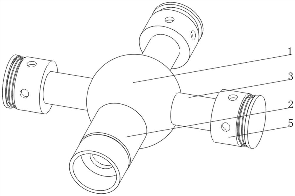
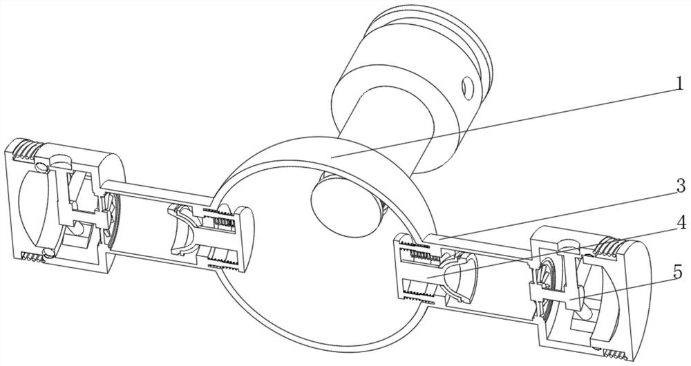
[0036] see Figure 1-3 , the present invention provides a technical solution: a sewage marine disposal and discharge device, specifically comprising:
[0037] Diverter spherical shell 1, the outer side of the diverter spherical shell 1 is respectively connected with water inlet pipe 2 and water outlet pipe 3, the end of the main water inlet pipe 2 far away from the diverter spherical shell 1 is connected with the sewage conveying pipeline, and the outlet pipe 3 is arranged in multiple groups and evenly distributed in the On the shunt spherical shell 1;
[0038] A blocking device 4, the blocking device 4 is arranged inside the water outlet pipe 3 near one end of the shunt spherical shell 1, and the blocking device 4 can block the water flow on one side;
[0039] A water outlet device 5, the water outlet device 5 is arranged at the end of the water outlet pipe 3 away from the shunt spherical shell 1, the water outlet device 5 can increase the impact force of the water flowing o...
Embodiment 2
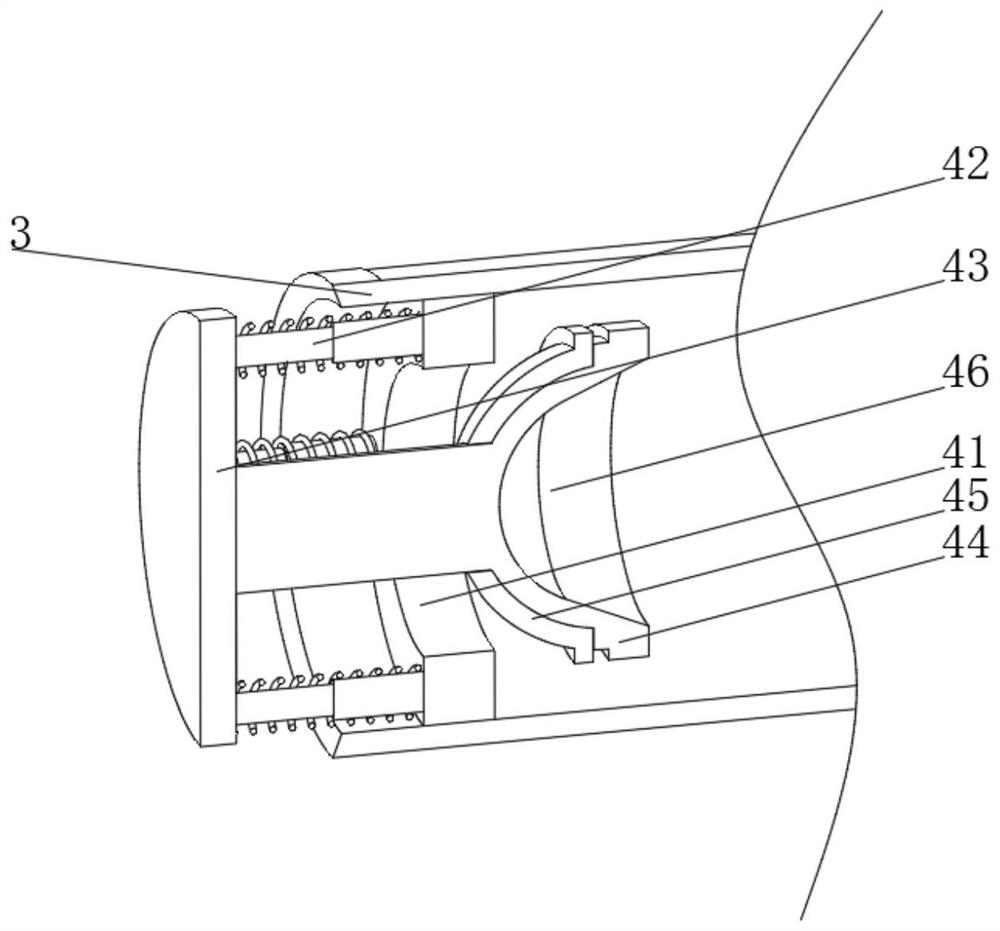
[0045] see Figure 1-4 On the basis of Embodiment 1, the present invention provides a technical solution: the water outlet device 5 includes a water outlet tray 51, a rotating ring 52 is arranged on one side of the water outlet tray 51, and the inner wall of the rotating ring 52 is fixedly connected with an inclined water retaining plate 53, and the inclined water retaining plate 53 is fixed on the inner wall of the rotating ring 52. The end of the water plate 53 away from the rotating ring 52 is fixedly connected with a rotating seat 54, and one end of the rotating seat 54 extends to the inner center of the water outlet tray 51. Sliding plate 55, the side of the inner wall of the water outlet tray 51 is provided with a water outlet hole 56 that is compatible with the arc-shaped slide plate 55, and the side of the water outlet tray 51 away from the rotating circle 52 is provided with an auxiliary water outlet device 57. When the sewage passes through the water outlet device 5, ...
Embodiment 3
[0047] see Figure 1-5 On the basis of the first and second embodiments, the present invention provides a technical solution: the auxiliary water outlet device 57 includes a plug 571, the outer side of the plug 571 is provided with a tension spring 572, and one end of the plug 571 is provided with a groove 573 Arc springs 574 are arranged on both sides of the end of the plug 571 close to the groove 573, the plug 571 is arranged on one side of the inner wall of the water outlet tray 51 and is slidably connected with the inner wall of the outlet tray 51, and the tension spring 572 is arranged between the plug 571 and the inner wall of the outlet tray 51. Between the water outlet trays 51, the inner wall of the water outlet tray 51 is provided with an arc-shaped slot matching the arc-shaped spring 574, and an auxiliary water outlet device 57 is provided. Card owner, when the water pressure inside the water outlet tray 51 gradually increases, the thrust received by the plug 571 al...
PUM
 Abstract
Description
Claims
Application Information
 - R&D
- Intellectual Property
- Life Sciences
- Materials
- Tech Scout
- Unparalleled Data Quality
- Higher Quality Content
- 60% Fewer Hallucinations
Browse by: Latest US Patents, China's latest patents, Technical Efficacy Thesaurus, Application Domain, Technology Topic, Popular Technical Reports.
© 2025 PatSnap. All rights reserved.Legal|Privacy policy|Modern Slavery Act Transparency Statement|Sitemap|About US| Contact US: help@patsnap.com