Polishing mechanism for robot machining
A technology of robot processing and grinding mechanism, which is applied in the direction of program control, instrument and general control system in the sequence/logic controller, which can solve the problems of large limitations, time-consuming and labor-intensive manual grinding, and low work efficiency, so as to improve the application Sexuality, maintenance of physical health, and reasonable structural design
- Summary
- Abstract
- Description
- Claims
- Application Information
AI Technical Summary
Problems solved by technology
Method used
Image
Examples
Embodiment 1
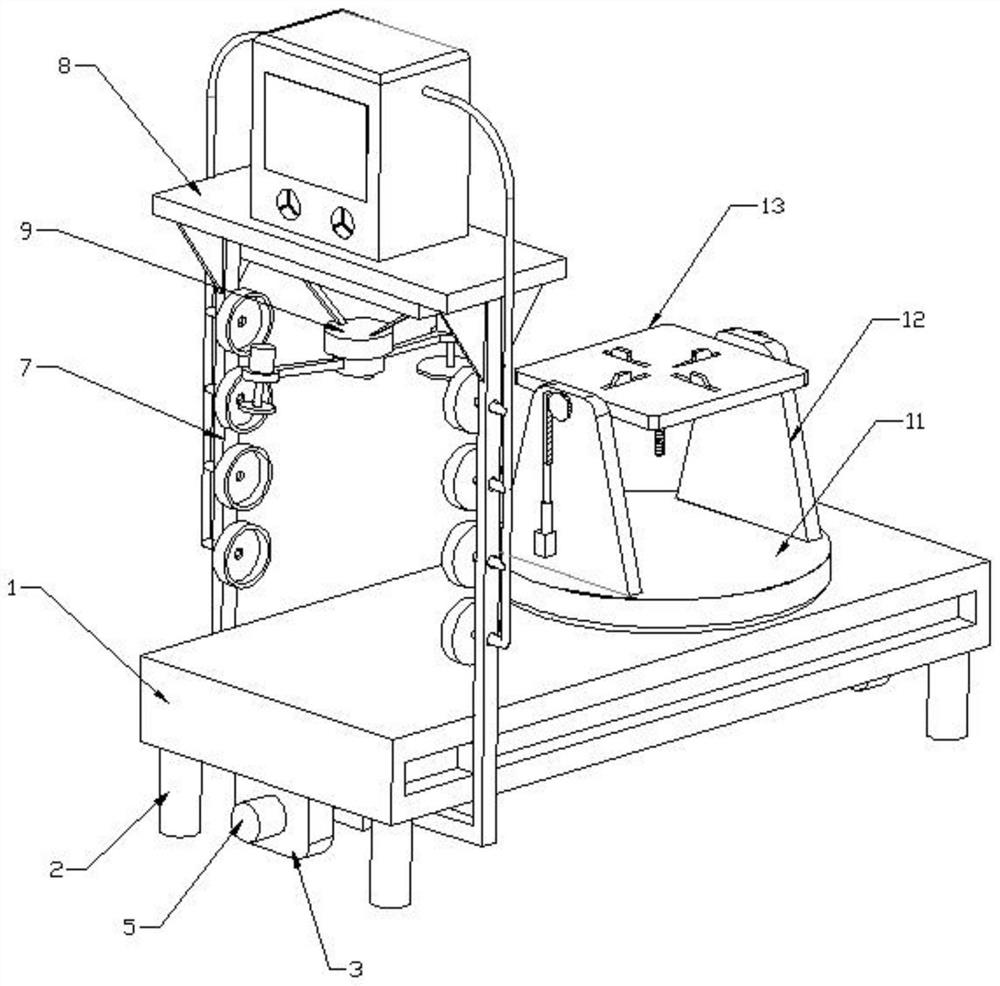
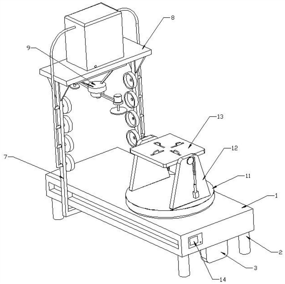
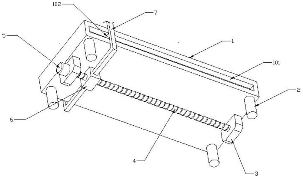
[0043] see Figure 1-10 As shown, this embodiment is a grinding mechanism for robot processing, including a workbench 1, the four corners of the bottom of the workbench 1 are connected with uprights 2, and the uprights 2 support the workbench 1, and the left and right sides of the bottom of the workbench 1 Fixed block 3 is connected, and screw mandrel 4 is connected with rotation between two fixed blocks 3, and the left end of screw mandrel 4 is connected with screw mandrel motor 5, and the outer wall of screw mandrel 4 is screwed with nut seat 6, and the front and back of nut seat 6 two The ends are symmetrically connected with a support frame 7, and the upper ends of the two support frames 7 are connected with a horizontal plate 8. The screw motor 5 is used to drive the screw 4 to rotate, so that the nut seat 6 drives the support frame 7 to move left and right, and the horizontal plate 8 can be adjusted. Horizontal position, the bottom of the horizontal plate 8 is connected ...
Embodiment 2
[0048] On the basis of Embodiment 1, the grinding frame 913 is set in a V-shaped structure, and the V-shaped angle of the grinding frame 913 is 120-125 degrees. 9132, the bottom of the inner cavity of the circular housing 910 is connected to the side bracket 9133, the end of the fixed shaft 9132 is connected to the side bracket 9133 through bearing rotation, the middle part of the outer wall of the fixed shaft 9132 is connected to the worm wheel 9134, and the bottom of the circular housing 910 is connected to the worm motor 9135, the power output end of the worm motor 9135 is connected with a worm screw 9136, the worm screw 9136 meshes and connects with the worm wheel 9134, the left and right sides of the bottom of the grinding frame 913 are connected with a push switch 9137, and the push switch 9137 is connected in series with the grinding motor 914 on the same side through a wire.
[0049] The unfolding helix angle of the worm 9136 is smaller than the friction angle of the co...
Embodiment 3
[0053] On the basis of Embodiment 1, the clamping assembly 13 includes a material setting table 131, and the material setting table 131 is provided with four guide grooves 132 in the circumferential direction, and a guide block 133 is slidably connected to the guide groove 132, and the upper end of the guide block 133 is connected to There is a clamping block 134, the lower end of the guide block 133 is hinged with a linkage rod 135, the center of the bottom of the material placing table 131 is connected with a driving motor 136, and the bottom power output end of the driving motor 136 is connected with a screw rod 137, and the outer wall of the screw rod 137 is screwed with a screw thread. The collar 138 , the lower ends of the four linkage rods 135 are hinged to the outer wall of the threaded collar 138 along the circumferential direction.
[0054] The overturn frame 12 includes two side plates 121, the upper end of the side plate 121 is rotatably connected with a driven shaf...
PUM
 Abstract
Description
Claims
Application Information
 - R&D
- Intellectual Property
- Life Sciences
- Materials
- Tech Scout
- Unparalleled Data Quality
- Higher Quality Content
- 60% Fewer Hallucinations
Browse by: Latest US Patents, China's latest patents, Technical Efficacy Thesaurus, Application Domain, Technology Topic, Popular Technical Reports.
© 2025 PatSnap. All rights reserved.Legal|Privacy policy|Modern Slavery Act Transparency Statement|Sitemap|About US| Contact US: help@patsnap.com


