Brain image processing

A processor and imaging technology, applied in the field of image processing, which can solve the problems of lack of clinical practicability and troublesome operation.

Pending Publication Date: 2021-11-12
OMNISCIENT NEUROTECH PTY LTD
View PDF0 Cites 0 Cited by
  • Summary
  • Abstract
  • Description
  • Claims
  • Application Information

AI Technical Summary

Problems solved by technology

However, current imaging systems are cumbersome to use and operate, and often produce outputs that lack clinical utility

Method used


Image

  • Brain image processing
  • Brain image processing
  • Brain image processing

Examples


Embodiment Construction

[0032] Where reference is made to steps and / or features with the same reference number in any one or more drawings, those steps and / or features have the same function or operate.

[0033] Glossary of terms

[0034]

[0035]

[0036]

[0037]

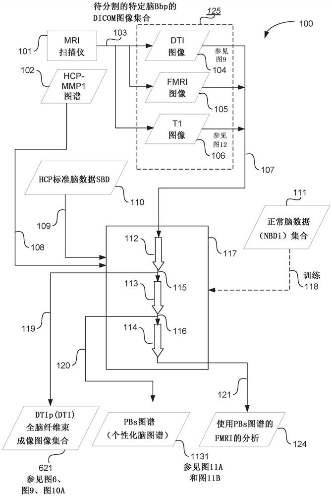
[0038] figure 1 A functional block and data flow diagram of an example 100 of a PAA arrangement for processing a collection of DICOM images is shown. As depicted by arrow 103, the MRI scanner 101 produces a set 125 of DICOM images of the brain Bbp to be segmented. The DICOM image set 125 includes a 4-dimensional (hereinafter referred to as 4D) set 104 of DTI images of Bbp (hereinafter referred to as Figure 9 described in more detail), a 4D set 105 of fMRI images of Bbp, and a 3D set 106 of T1 images of Bbp (referenced below Figure 12described in more detail. See Glossary of terms for more details on these image collections). As depicted by arrow 107, these image sets are provided to PAA processing module 117, hereinaf...


PUM


Abstract

A method (400) includes determining (702) a registration function [705, Niirf (T1)] for a particular brain in a coordinate space, determining (706) a registration map [708, Ard (T1)] from the registration function and an HCP-MMP1 map (102) including a standard segmentation scheme, performing (310, 619) diffusion fiber bundle imaging to determine a set of brain fiber bundle imaged images [621, DTIp (DTI)], determining (1105, 1120) a voxel-level fiber bundle imaging vector [1123, Vje, Vjn] showing the connection of the voxel to voxels in other partitions for a voxel in a particular partition in the registration map, classifying (1124) voxels based on the probability that the voxels are part of a particular segmentation, and repeating (413) the determination of voxel-level fiber bundle imaging vectors and the classification of voxels for the segmentation of the HCP-MMP1 map to form a personalized brain map [1131, PBs map] comprising an adjusted segmentation scheme reflecting a particular brain (Bbp).

Description

technical field [0001] The present invention relates generally to image processing, and in particular, to the processing of images of a subject's brain generated by a magnetic resonance imaging system. The invention also relates to a method and a device for processing images, and to a computer program product comprising a computer readable medium on which is recorded a computer program for processing images. Background technique [0002] Medical imaging using functional magnetic resonance imaging (fMRI) and diffusion tensor imaging (DTI) provide insights into the functional activity and structural connectivity of the brain, respectively. However, current imaging systems are cumbersome to use and operate, and often produce output that lacks clinical utility. Contents of the invention [0003] It is an object of the present invention to substantially overcome or at least improve one or more disadvantages of existing arrangements. [0004] Brain surgery often involves cutti...

Claims


Application Information

Patent Timeline
IPC IPC(8): G01R33/20G01R33/56G16H30/40
CPCG06T7/0012G01R33/56341G06T2207/20128G06T2207/30016G06T7/10G16H30/20G06T15/00G06N20/00G16H30/40G06T2210/41G06T2207/10088G01R33/5608G01R33/4806G06T2207/10092G06T2200/04G06T7/30G06T2207/20076G06T2207/20081G06T7/0014
Inventor 迈克尔·萨格鲁史蒂法纳·杜瓦扬查尔斯·特奥
Owner OMNISCIENT NEUROTECH PTY LTD
Why Eureka
Try Eureka