
Multifunctional electric hydraulic pipe fitting machining tool

A technology for processing tools and hydraulic pipes, which is applied in the field of multifunctional electro-hydraulic pipe fittings processing tools, can solve the problems of unguaranteed product quality, low processing efficiency, and high cost of use, and achieve compact and reasonable space structure, improved oil absorption efficiency, and extended service life Effect

Pending Publication Date: 2021-11-16
ZHEJIANG VALUE MECHANICAL & ELECTRICAL PROD CO LTD
View PDF5 Cites 2 Cited by
  • Summary
  • Abstract
  • Description
  • Claims
  • Application Information

AI Technical Summary

Problems solved by technology

[0003] The present invention mainly provides a multi-functional electro-hydraulic pipe fitting processing tool that can be used for processing various types of pipe fittings, has good versatility, saves time and labor, is convenient to carry and use, and solves the problem of pipe fitting processing in the prior art. The tool has a single function, high cost of use, and is generally operated manually. The processing process is not only time-consuming and labor-intensive, the processing efficiency is low, and the product quality cannot be guaranteed.

Method used

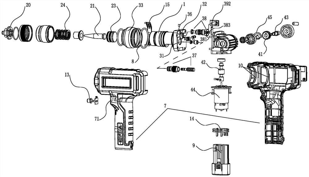
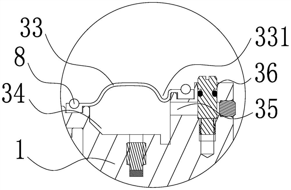
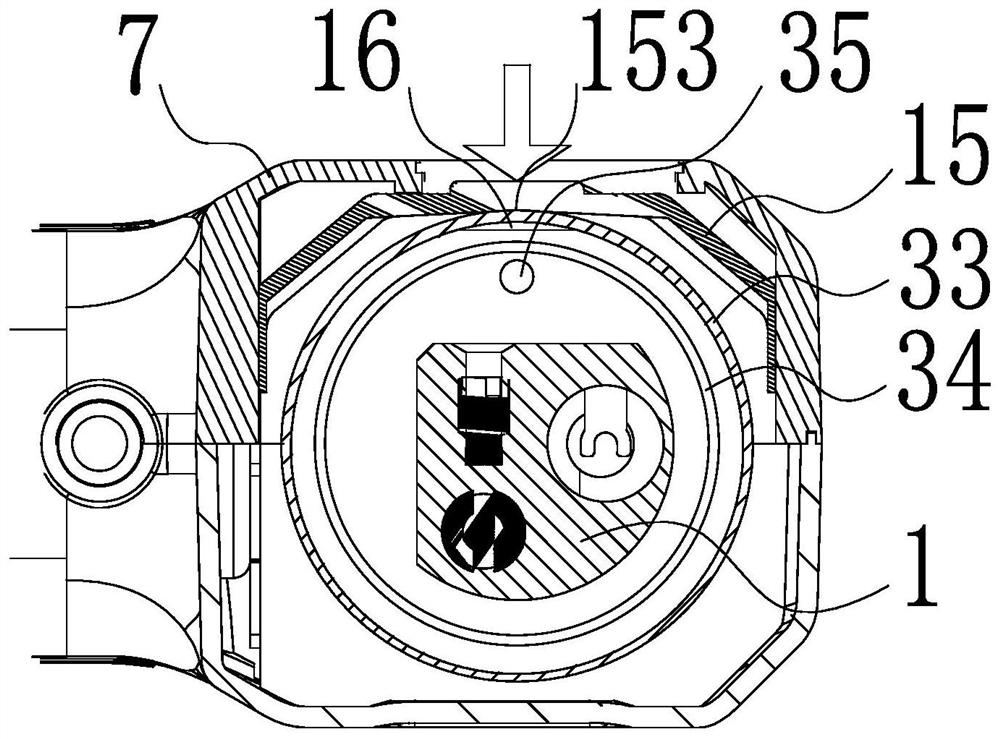

Image

  • Multifunctional electric hydraulic pipe fitting machining tool
  • Multifunctional electric hydraulic pipe fitting machining tool
  • Multifunctional electric hydraulic pipe fitting machining tool

Examples


Embodiment 1

[0061] Such as figure 1 As shown, a multifunctional electro-hydraulic pipe fitting processing tool of the present invention includes a housing 7 similar to a "7" shape and a body 1 inside the housing 7. The front end of the body 1 has a feeding mechanism, and the rear end has a The hydraulic mechanism has a drive mechanism below the rear end, wherein the feed mechanism includes a drive chamber 22 located at the front end of the body 1, the port of the drive chamber 22 is externally screwed to the cone head cover ring 27, and the cone head cover ring 27 is coaxially docked and installed The pipe fitting chuck 20, the pipe fitting chuck 20 in this embodiment is the expansion head, the cone head 21 is the pipe expansion cone head, the cone head 21 is slidably connected in the drive chamber 22 through the piston 23, and the driving mechanism pushes the cone head through the hydraulic mechanism 21 move to the outside of the cone head cover ring 27, and process the pipe fittings cla...

Embodiment 2

[0075] The pipe fitting chuck 20 is coaxially docked on the cone head cover ring 27. The pipe fitting chuck 20 in this embodiment is a pipe expansion head, and the cone head 21 is a pipe expansion cone head. The pressure relief shift fork 392 in the embodiment is removed, as Figure 4 As shown, one end of the L-shaped elastic fork 391 is slidably connected to the chuck groove 383, and the end of the elastic fork 391 corresponding to the bottom surface of the chuck groove 383 has a U-shaped notch groove that matches each other, and the elastic fork 391 passes through The U-shaped notch grooves are interfitted and clamped in the chuck groove 383, and there is a gap between the inner surface of the elastic shift fork 391 and the corresponding inner ring wall of the chuck groove 383, and the other end of the elastic shift fork 391 is located at the oil storage ring. 33, the body 1 close to the spool 381 extends outward to form a fork fulcrum 19 that can support the elastic fork 391...

Embodiment 3

[0077] The pipe fitting chuck 20 is coaxially docked on the cone head cover ring 27. The pipe fitting chuck 20 in this embodiment is a pressure pipe head, and the cone head 21 is a pressure pipe cone head, such as Figure 12As shown, a retaining ring 28 is sandwiched between the inner end of the return spring 24 and the outer end surface of the piston 23, the retaining rings 28 are matched with each other on the cone head 21, and the inner ring surface of the retaining ring 28 extends to the outside of the cone head 21. The ring surface, the outer ring surface of the retaining ring 28 extends forward along the outer ring surface of the return spring 24 to form an L shape, the outer side of the front end of the return spring 24 is equipped with a booster spring 25, and the direction of rotation of the return spring 24 and the booster spring 25 is opposite. And the rigidity of back-moving spring 24 is less than the rigidity of booster spring 25, and booster spring 25 is positione...


PUM


Abstract

The invention discloses a pipe fitting machining tool, and provides a multifunctional electric hydraulic pipe fitting machining tool which can be used for machining various types of pipe fittings, is good in universality, saves time and labor in machining and is convenient to carry and use. The technical problems that in the prior art, a pipe fitting machining tool is single in function and high in use cost, generally manual operation is used, the machining process wastes time and consumes labor, the machining efficiency is low, and the product quality cannot be guaranteed are solved. The multifunctional electric hydraulic pipe fitting machining tool comprises a body, and a feeding mechanism, a hydraulic mechanism and a driving mechanism that are arranged on the body, a driving motor on the driving mechanism is electrically connected to a battery pack, the driving mechanism pushes a conical head in the feeding mechanism to move outwards through the hydraulic mechanism to be matched with a pipe fitting chuck, the hydraulic mechanism comprises a plunger cavity and a pressure relief cavity which are in communication with the rear end of the conical head, the plunger cavity and the pressure relief cavity are in communication with an oil storage ring covering the body, and the strength of the oil storage ring wall face close to an inlet of the plunger cavity is increased.

Description

technical field [0001] The invention relates to a pipe fitting processing tool, in particular to a pipe fitting processing tool which can be used for various types of pipe fittings. It is a multifunctional electro-hydraulic pipe fitting processing tool that reduces the flow resistance of hydraulic oil and improves oil absorption efficiency. Background technique [0002] Existing pipe fitting processing tools, such as pipe expanders, pipe expanders and pipe crimpers, often only have a single function. For example, pipe expanders can only be used for pipe expansion processing of pipe fittings, and pipe expanders can only be used for pipe expansion of pipe fittings. Processing, the pipe crimping device can only be used for pipe crimping processing of pipe fittings. Therefore, in order to meet the needs of use, users need to be equipped with a variety of tools, which are expensive to use and inconvenient for storage and transportation. At the same time, the above-mentioned pipe ...

Claims


Application Information

Patent Timeline
IPC IPC(8): B21D39/20B21D41/02B21D55/00B30B1/32B30B15/04B30B15/26
CPCB21D41/028B21D39/20B21D55/00B30B1/32B30B15/04B30B15/26
Inventor 蒋友荣
Owner ZHEJIANG VALUE MECHANICAL & ELECTRICAL PROD CO LTD
Learn More