
Oil absorption device for ocean oil contamination treatment

An oil pollution and marine technology, which is used in open water surface cleaning, water conservancy projects, general water supply conservation, etc., can solve problems such as unclean suction, hidden safety hazards in combustion processing, and loss of containment control, so as to improve oil absorption efficiency and shorten oil absorption time. Effect

Active Publication Date: 2015-12-02
孙勇
View PDF8 Cites 3 Cited by
  • Summary
  • Abstract
  • Description
  • Claims
  • Application Information

AI Technical Summary

Problems solved by technology

But there are the following problems: the former's drag bar is almost completely floating on the water surface, and when there are slight waves on the water surface, it will slide over the oil spill surface and lose its confinement effect. Practical problems; the latter has low single-chip delivery and recovery efficiency, and also has practical problems such as small adsorption contact surface, slow speed, and unclean suction.
The melt-blown polypropylene oil-absorbing drag rail and oil-absorbing felt after actual use contain about 10-20% saline seawater. The saline oil product has no use value in subsequent treatment, and there is also a major safety hazard in burning treatment, so it can only be used as landfill , easy to cause secondary pollution

Method used


Image

  • Oil absorption device for ocean oil contamination treatment
  • Oil absorption device for ocean oil contamination treatment
  • Oil absorption device for ocean oil contamination treatment

Examples


Embodiment 1

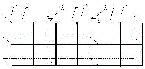
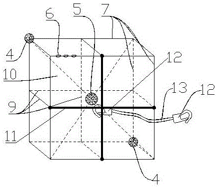
[0038] The oil-absorbing device for marine oil pollution control includes a plurality of oil-absorbing units 1 interconnected by buckles 8 , and the oil-absorbing unit 1 includes a unit outer frame 2 and an oil-absorbing core package 3 placed in the unit outer frame 2 . Wherein, the structure of the single outer frame 2 is as follows: figure 2 As shown, the specific structure is as described above.

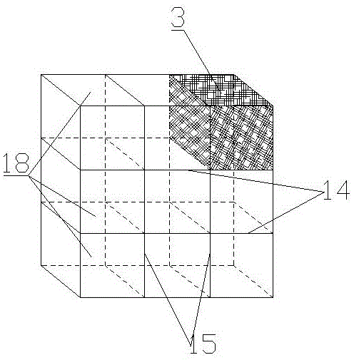
[0039] Such as image 3 As shown, the oil-absorbing core package 3 is composed of expanded graphite particles and a waterproof and oil-permeable non-woven fabric layer 20 wrapped outside the expanded graphite particles. There are multiple storage units inside the single outer frame 2 18 partitions, each storage unit 18 is provided with an oil-absorbing core bag 3, and the partition is composed of a horizontal partition 14 and a vertical partition 15 arranged vertically to each other, the horizontal partition 14 and the vertical partition 15 The numbers are the same, the specifi...

Embodiment 2

[0042] Oil absorption devices for marine oil pollution control, such as figure 1 As shown, it includes a plurality of oil-absorbing units 1 connected to each other by buckles 8. The oil-absorbing unit 1 includes a unit outer frame 2 and an oil-absorbing core package 3 placed in the unit outer frame 2, wherein the unit outer frame 2 The structure is as figure 2 As shown, the specific structure is as described above.

[0043] Such as Figure 4 As shown, the oil-absorbing core pack 3 includes a frame body 21 and a waterproof and oil-permeable non-woven fabric layer 20 wrapped outside the frame body 21. The frame body 21 is internally provided with a plurality of compartments that divide its inner cavity into a plurality of storage units 18. Divider, the divider is provided with a plurality of holes 19, and expanded graphite particles are placed in each storage unit 18, and the divider is composed of a horizontal divider 16 and a vertical divider 17 arranged perpendicular to ea...

Embodiment 3

[0046] Oil absorption devices for marine oil pollution control, such as figure 1 As shown, it includes a plurality of oil-absorbing units 1 connected to each other by buckles 8. The oil-absorbing unit 1 includes a unit outer frame 2 and an oil-absorbing core package 3 placed in the unit outer frame 2, wherein the unit outer frame 2 The structure is as figure 2 As shown, the specific structure is as described above.

[0047] Such as Figure 4 As shown, the oil-absorbing core pack 3 includes a frame body 21 and a waterproof and oil-permeable non-woven fabric layer 20 wrapped outside the frame body 21. The frame body 21 is internally provided with a plurality of compartments that divide its inner cavity into a plurality of storage units 18. Divider, the divider is provided with a plurality of holes 19, and expanded graphite particles are placed in each storage unit 18, and the divider is composed of a horizontal divider 16 and a vertical divider 17 arranged perpendicular to ea...


PUM


Abstract

Disclosed is an oil absorption device for ocean oil contamination treatment. The oil absorption device comprises a plurality of oil absorption single bodies which are connected with one another through retaining rings. Each oil absorption single body comprises a single body outer framework and an oil absorption core bag placed in the single body outer framework. Expanded graphite particles are contained in each oil absorption core bag. Two balance weight devices are arranged at the symmetrical positions of the lowermost portion of each single body outer framework, and the specific value of the total weight of the two balance weight devices to the displacement of the corresponding oil absorption single body is 1:5 to 1:10. The oil absorption device works at the interface of water and oil all the time by adding the variable balance weight devices through buoyancy calculation; dynamic adsorption is formed by dragging a dragging rope, and the absorption speed is increased; through experimental determination, the oil absorption efficiency is improved by more than four times. The oil absorption device has the actual effects of being high in treatment speed and high in absorption cleanliness on ultrathin water surface spillage oil commonly happening to oil spillage treatment; meanwhile, the device has the advantages that stretching resistance and impact resistance are achieved and the device can be suspended.

Description

technical field [0001] The invention relates to the technical field of marine oil pollution control, in particular to an oil absorbing device for marine oil pollution control. Background technique [0002] The main pollutant of marine pollution is petroleum hydrocarbon oil pollution, which can cause hypoxia and poisoning of water bodies, cause loss of coastal wetland area, and cause harm to industrial and agricultural production such as fishery, salt industry, and seawater desalination. There are generally two ways to clean up traditional marine oil pollution adsorption products: first, use soft melt-blown polypropylene material as the core body, and outsource PVC and other plastic mesh bag materials to make long cylindrical oil-absorbing drag rails; Spray polypropylene material to make a square oil-absorbing felt with a thickness of about 1-2mm and a square of 30-50cm, and its oil absorption is 10 to 20 times its own weight. But there are the following problems: the former...

Claims


Application Information

Patent Timeline
Patent Type & Authority Applications(China)
IPC IPC(8): E02B15/10
CPCY02A20/204
Inventor 孙勇孙娟沈万慈
Owner 孙勇
Learn More