3D (Three-dimensional) printing method for metal/ceramic powder sintering partition

A 3D printing, ceramic powder technology, applied in the field of parts preparation, can solve the problems of easy collapse of parts, time-consuming degreasing process, etc., to achieve the effect of ensuring structural strength

Pending Publication Date: 2021-11-16
EZHOU INST OF IND TECH HUAZHONG UNIV OF SCI & TECH +1
View PDF12 Cites 2 Cited by
  • Summary
  • Abstract
  • Description
  • Claims
  • Application Information

AI Technical Summary

Problems solved by technology

[0005] This application provides a 3D printing method for metal / ceramic powder sintering partitions to solve the time-consuming degreasing process and the easy collapse of parts after the sintering process caused by the use of existing binders

Method used


Image

  • 3D (Three-dimensional) printing method for metal/ceramic powder sintering partition
  • 3D (Three-dimensional) printing method for metal/ceramic powder sintering partition
  • 3D (Three-dimensional) printing method for metal/ceramic powder sintering partition

Examples


Embodiment 1

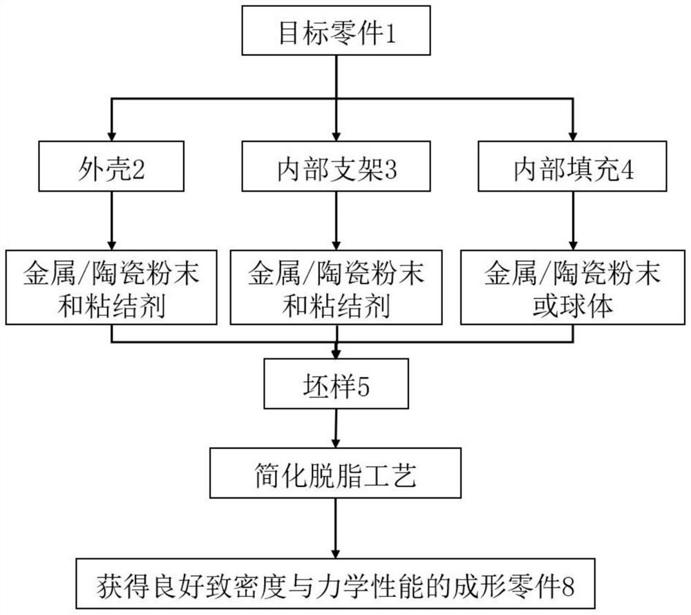
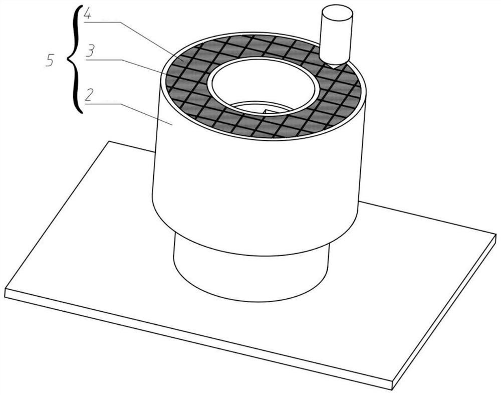
[0079] The technical method of this embodiment 1 is based on the deposition technology of metal paste 3D printing; based on the partition method and the three-dimensional model, the model of the target part is divided into three parts: the shell 2, the internal bracket 3, and the filling area 4, and the shell 2 is of equal thickness. The shell and the internal bracket 3 are grid-shaped; when manufacturing each layer of the part blank 5, the metal paste made by mixing metal powder and polymer binder is used to melt the shell 2 and the internal bracket 3 Deposit single-layer printing to ensure that the part blank has a good bearing capacity; then use a powder dropping device or a powder spreading device to print the filling area 4 of the layer blank 5 with metal powder; print layer by layer, and finally obtain a metal powder that is much larger than The printed blank sample of the binder 5; due to the significant reduction of the binder components, the required degreasing process...

Embodiment 2

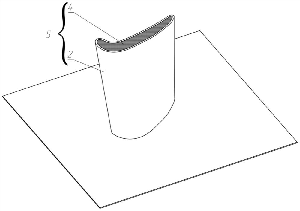
[0081] This embodiment 3 is the same as embodiment 1, but when forming small parts or thin walls, the divided shell 2 has sufficient strength to bear the self-weight of the parts of the blank sample 5 and the shrinkage stress of the printing process, and the internal support 3 is used and filled Area 4 is printed with exactly the same material, that is, the area of ​​the inner bracket 3 is not divided; when manufacturing each layer of the part blank, the metal paste made by mixing metal powder and polymer binder is first used for the shell 2 Single-layer printing ensures that the blank 5 of the part has a good bearing capacity; then uses metal powder to print the filling area 4 of the blank 5 of this layer; prints layer by layer, and finally obtains the printed blank 5 with a metal powder ratio much larger than that of the binder ;Such as image 3 shown.

Embodiment 3

[0083]Embodiment 3 is the same as Embodiment 1, but the internal support 3 adopts a lattice structure for model building and path planning, such as a body-centered cubic (BCC) structure 301 in a lattice structure after fillet optimization; a known lattice structure The bearing capacity per unit mass is much higher than that of other traditional structures. In this partitioning method, the proportion of metal powder in blank sample 5 will be greatly increased, so as to improve the density of formed parts and reduce the sintering shrinkage rate; Figure 4 shown.


PUM

PropertyMeasurementUnit
particle diameteraaaaaaaaaa
diameteraaaaaaaaaa

Abstract

The invention belongs to the technical field of part preparation, and provides a 3D (Three-dimensional) printing method for metal / ceramic powder sintering partition. The method comprises the following steps of acquiring a three-dimensional model of a target part; according to the outer contour offset curved surface of the target part and the three-dimensional model, constructing a printing model with a supporting area and a filling area for the target part; and sequentially printing the supporting area and the filling area layer by layer through the printing model. A prepared blank sample is subjected to a shorter degreasing procedure and a shorter sintering procedure, so that a part with higher density and better mechanical property can be obtained. The 3D printing method for metal / ceramic powder sintering partition provided by the invention also solves the problem that the structural strength of the blank sample is weakened due to the change of the forming method, and the problems that the structure is loose and easy to collapse after a binder is removed through degreasing and the like.

Description

technical field [0001] The invention belongs to the technical field of parts preparation, and provides a 3D printing method for metal / ceramic powder sintering partitions. Background technique [0002] In the 3D printing system, metal 3D printing technology is the most cutting-edge and most potential technology. In the mainstream metal 3D printing technology, high-energy beam heat sources such as lasers and electron beams are required to melt metal powder. The requirements for the forming environment of parts are high, and the cost of equipment and manufacturing remains high. The metal slurry deposition forming technology (CN103801697A) and the selective binder micro-spray forming technology (US5766304A) for the metal powder layer can be used to prepare the blank sample mixed with metal powder and polymer binder directly. , and then the binder is removed through the degreasing process, and the metal powder is sintered in the sintering process, so that metal parts can be obta...

Claims


Application Information

Patent Timeline
Patent Type & Authority Applications(China)
IPC IPC(8): B22F10/10B22F10/14B28B1/00B33Y10/00B33Y70/10
CPCB22F10/14B22F10/10B28B1/001B33Y10/00B33Y70/00Y02P10/25
Inventor 王泽敏兰新强李祥友李树寒贺兵李桐
Owner EZHOU INST OF IND TECH HUAZHONG UNIV OF SCI & TECH
Why Eureka
Try Eureka