
Composite board production line

A composite board and production line technology, applied in the direction of layered products, lamination devices, lamination, etc., can solve the problems of glue curing in the glue spraying device, affecting the quality of glue spraying, affecting production efficiency, etc., to reduce the floor area, The effect of improving the quality of glue spraying and high production efficiency

Inactive Publication Date: 2021-11-16
泉州市益达机械制造有限公司
View PDF0 Cites 1 Cited by
  • Summary
  • Abstract
  • Description
  • Claims
  • Application Information

AI Technical Summary

Problems solved by technology

However, the above-mentioned composite board production line directly installs the glue spraying device on the conveying device. However, during the use of the glue spraying device, glue will inevitably drip onto the conveying device, and frequent cleaning is required to avoid the glue on the conveying device from polluting the composite board. The quality of glue spraying is affected by the non-glue-spraying surface of the board, and the production efficiency is relatively low; in addition, because the pressing device needs to press the composite board for a period of time to ensure heat transfer, and then realize the pressing and shaping, it takes a relatively long time. However, the previous processes such as glue spraying and plate turning can usually achieve continuous operation or short-term intermittent operation, and the time-consuming is relatively short. Therefore, it is necessary to stop the machine and wait for the pressing device, which not only affects production efficiency, but also easily leads to failure of the glue spraying device. The glue at the glue outlet part is solidified, which affects the quality of glue spraying

Method used


Image

  • Composite board production line
  • Composite board production line
  • Composite board production line

Examples


Embodiment Construction

[0036] The present invention will be further described below in conjunction with the accompanying drawings and specific embodiments.

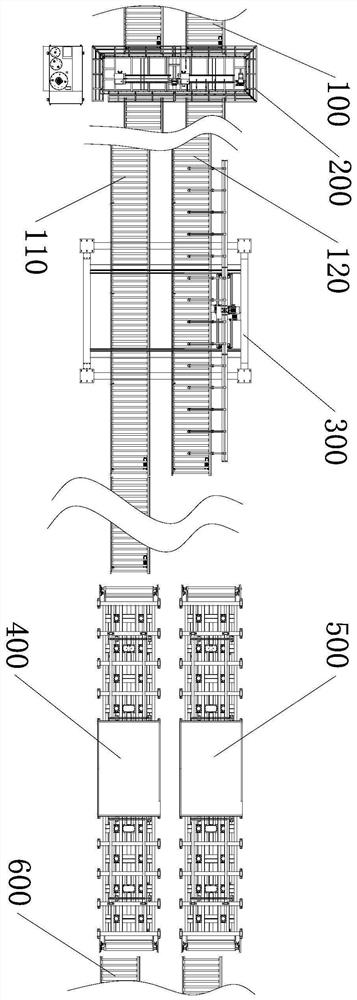
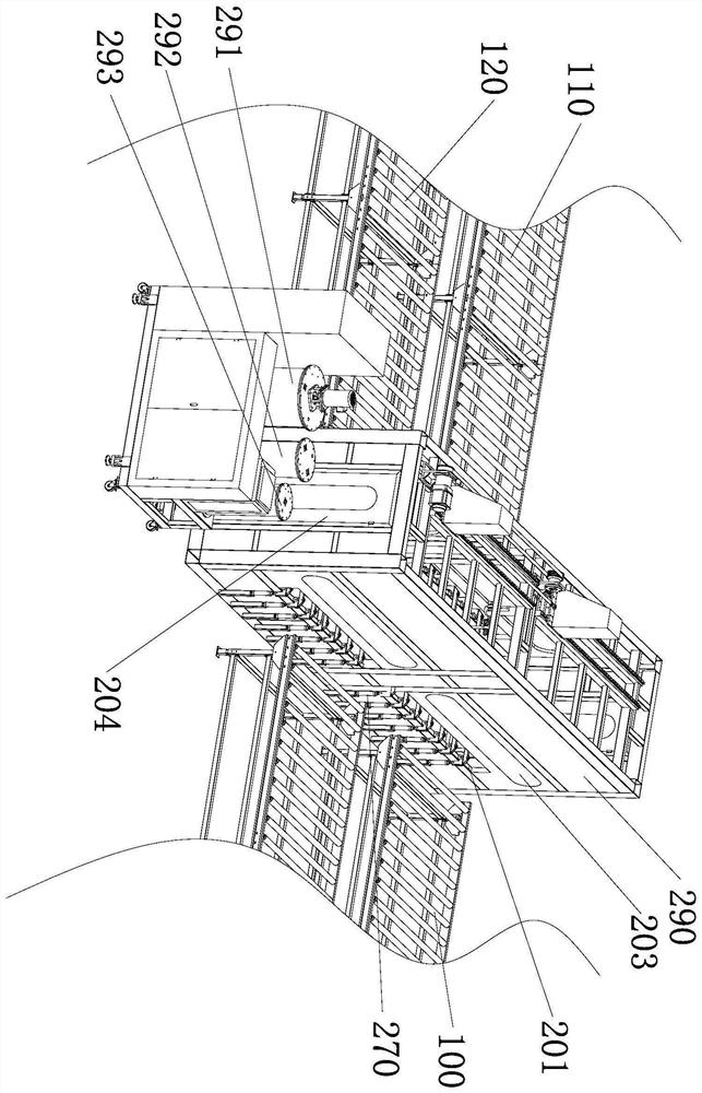
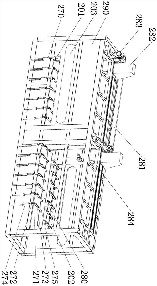
[0037] Such as figure 1 As shown, this embodiment provides a composite board production line, including two side-by-side board feeding conveying devices 100 and a first glue spraying machine 200 connected with the two board feeding conveying devices 100 at the same time, the first glue spraying machine 200 is far away from The first conveying device 110 and the second conveying device 120 are connected to one side of the two plate feeding conveying devices 100 at the same time, and the first conveying device 110 and the second conveying device 120 are respectively arranged in one-to-one correspondence with the two plate feeding conveying devices 100, The conveying devices corresponding to each other are located on the same straight line. When in use, the ends of the two feeding conveying devices 100 away from the first glue spraying machine 20...


PUM


Abstract

The invention provides a composite board production line which comprises a board feeding conveying device and a first glue spraying machine, one side of the first glue spraying machine is connected with a first conveying device and a second conveying device at the same time, and a board combining device is arranged beside the first conveying device. The end, away from the first glue spraying machine, of the first conveying device is connected with a first hot press, and a second hot press is arranged beside the first hot press side by side. And one end, relatively close to the first glue spraying machine, of the second hot press is provided with a board feeding ferry vehicle used for conveying a composite board located on the first conveying device to the second hot press. The conveying devices are arranged on the two sides of the first glue spraying machine, and compared with a traditional technical scheme that the conveying devices directly penetrate through the glue spraying machines, the situation that glue drips onto the conveying devices to affect the glue spraying quality is avoided, frequent cleaning of the conveying devices is also avoided, the glue spraying quality is relatively good, and the production efficiency is relatively high.

Description

technical field [0001] The invention relates to a composite board production equipment, in particular to a composite board production line. Background technique [0002] Composite board is a board composed of layers of different materials with different functions. According to its material, it can be generally divided into metal composite board, color steel composite board, rock wool composite board and so on. The Chinese invention patent application discloses a color steel composite panel production line, which includes a top plate conveying device and a bottom plate conveying device. The top plate conveying device and the bottom plate conveying device are respectively provided with a discharging device, a forming device, a top plate conveying device and a bottom plate in sequence along the conveying direction. The conveying device is located at the rear of each forming device and is also equipped with a glue spraying device; it also includes a turning device and a pressing...

Claims


Application Information

Patent Timeline
Patent Type & Authority Applications(China)
IPC IPC(8): B32B37/12B32B37/06B32B37/10B05C5/00B05C13/02B05C11/10B05B15/55
CPCB32B37/12B32B37/06B32B37/10B05C5/00B05C13/02B05C11/10B05B15/55
Inventor 谢志明
Owner 泉州市益达机械制造有限公司
Learn More