Laminated slab, connecting structure of laminated slab and composite beam and construction method

A technology for connecting structures and construction methods, which is applied in the direction of load-bearing elongated structural members, structural elements, truss-type structures, etc. The effect of shear performance, high construction efficiency and low reinforcement consumption

Pending Publication Date: 2021-11-16
筑友智造建设科技集团有限公司
View PDF11 Cites 4 Cited by
  • Summary
  • Abstract
  • Description
  • Claims
  • Application Information

AI Technical Summary

Problems solved by technology

However, the laminated floor slab also has obvious disadvantages. The rigidity of the prefabricated floor slab is small, and it is easy to crack during hoisting and transportation, which greatly limits its application.
In view of this, the reinforced truss laminated slab proposed by the Chinese patent CN201320114445.3 overcomes the above-mentioned shortcomings of the laminated floor slab, but has the following disadvantages: the amount of truss reinforcement is large, which only improves the rigidity of the prefabricated slab. The impact on performance is small, the waste of steel bars is serious, and the cost is also greatly increased
Chinese patent CN201620040756.3 proposes a laminated slab with concrete ribs. Although it can effectively improve the stiffness of the prefabricated floor, the connection between the floor and the ribs is relatively complicated, and the production of the laminated slab requires secondary pouring. brings difficulties
During the construction of traditional composite beams, the concrete slabs are often cast-in-place construction methods, but this method requires complex formwork installation and removal on site, and the construction efficiency is low, and the environmental pollution is relatively large
Chinese patent CN201920120142.X proposes a laminated slab composite beam, but it has the following disadvantages: the rigidity of the prefabricated slab is small, and the prefabricated slab is easy to crack during transportation and hoisting
Patent CN201910072931.5 is also a laminated slab composite beam. The prefabricated slab is provided with truss reinforcement. The truss reinforcement can be simplified as a rib on the prefabricated slab, which can effectively improve the rigidity of the prefabricated slab and greatly reduce the prefabricated slab. The risk of cracking during transportation and hoisting; but there are problems: the amount of truss reinforcement is very large, which has little impact on the mechanical performance of the composite beam after the laminated layer is poured, the waste of reinforcement is serious, and the cost is also greatly increased

Method used


Image

  • Laminated slab, connecting structure of laminated slab and composite beam and construction method
  • Laminated slab, connecting structure of laminated slab and composite beam and construction method
  • Laminated slab, connecting structure of laminated slab and composite beam and construction method

Examples


Embodiment 1

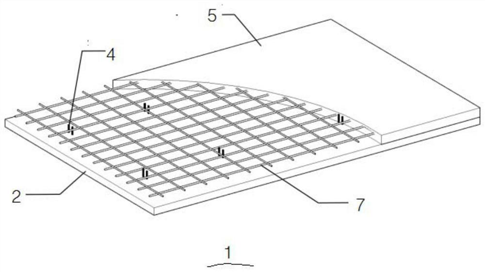
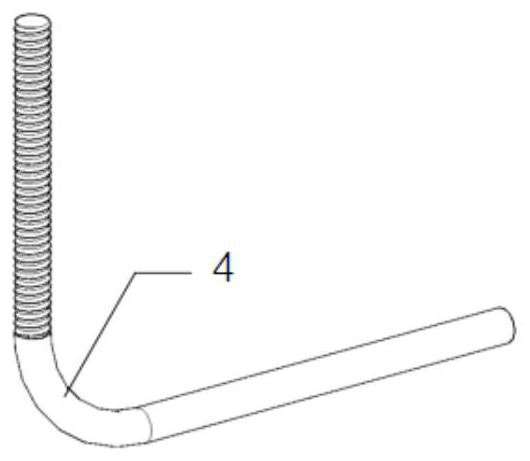
[0045] See attached figure 1 To attach figure 2For illustration, the laminated slab 1 in this embodiment includes a prefabricated layer and a post-cast layer 3, and the prefabricated layer includes a prefabricated floor 2 and a plurality of shear reinforcement bars 4, and the bottom ends of the plurality of shear reinforcement bars 4 are all anchored in the prefabricated floor 2 , the tops are all exposed on the prefabricated bottom plate 2, the post-cast layer 3 includes post-cast concrete 5 and surface layer reinforcement 6, the surface layer reinforcement 6 is arranged on the upper surface of the precast layer, and the post-cast concrete 5 is poured on the upper surface of the prefabricated bottom plate 2. The tops of the first shear bars 4 and the surface layer bars 6 are all anchored in the post-cast concrete 5 . In this embodiment, the two ends of the shear reinforcement 4 are respectively anchored in the prefabricated layer and the post-cast layer 3. By setting the sh...

Embodiment 2

[0048] See attached image 3 to attach Figure 7 , the connection structure between the laminated slab 1 and the composite beam 10 in this embodiment includes the laminated slab 1 and the composite beam 10 in Embodiment 1, and the composite beam 10 includes a steel beam 8 and a plurality of pegs fixed on the surface of the steel beam 8 9. The bottom surface of one side of the prefabricated layer rests on the upper surface of the steel beam 8, the post-cast concrete 5 on the precast layer fills the joint between the steel beam 8 and the precast layer, and the studs 9 are anchored to the post-cast concrete at the joint 5 in. See attached Figure 7 For illustration, the composite beam 10 in this embodiment welds a row of studs 9 on the surface of the steel beam 8, so that the studs 9 are anchored in the post-cast layer 3 of the laminated slab 1, which improves the connection between the composite beam 10 and the laminated slab. 1, the prefabricated layer of the laminated slab ...

Embodiment 3

[0059] See attached Figure 8 And attached Figure 9 , the present embodiment is the construction method of the connection structure between the laminated slab 1 and the composite beam 10 in the improved example of embodiment 2, comprising the following steps:

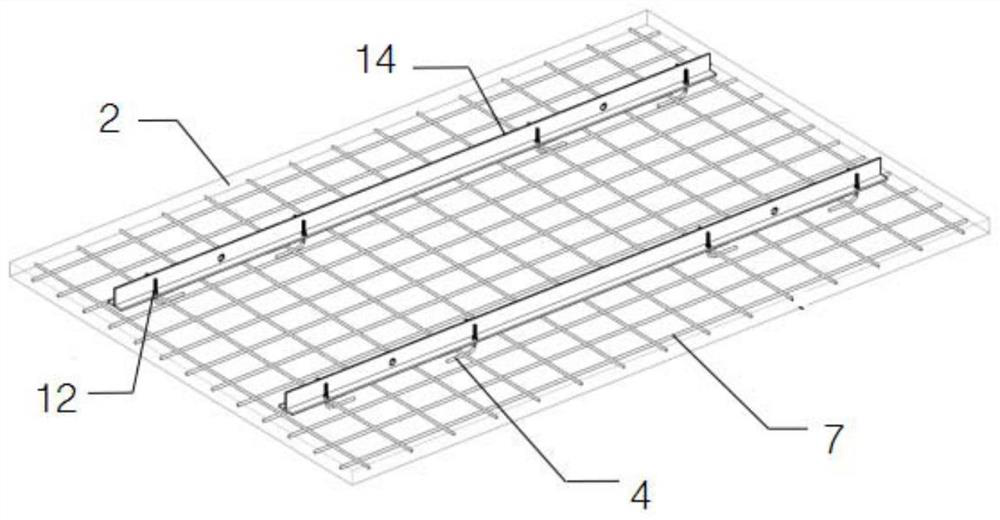
[0060] S1. Production of prefabricated layers: Lay reinforcement mesh 7 and shear reinforcement 4, pour concrete for prefabricated bottom slab 2 and maintain and form, install multiple detachable ribs on the upper surface of prefabricated bottom slab 2, and the top of shear reinforcement 4 passes through detachable The rib, the fixing part is connected with the top of the shear steel bar 4 to fix the detachable rib on the prefabricated bottom plate 2;

[0061] S2. Set vertical support, lift the composite beam 10 and position it on the vertical support, use the detachable rib as the lifting point to lift the first prefabricated layer and the second prefabricated layer respectively, and the first prefabricated layer and...


PUM


Abstract

The invention discloses a laminated slab, a connecting structure of the laminated slab and a composite beam and a construction method. The laminated slab comprises a prefabricated layer and a post-pouring layer, the prefabricated layer comprises a prefabricated bottom plate and a plurality of shear reinforcements, the post-pouring layer comprises post-pouring concrete and surface layer reinforcements, the post-pouring concrete is poured on the prefabricated bottom plate, and the top ends of the shear reinforcements and the surface layer reinforcements are anchored in the post-pouring concrete. The connecting structure of the laminated slab and the composite beam comprises the laminated slab and the composite beam, the composite beam comprises a steel beam and studs, the prefabricated layer is placed on the steel beam, and a splicing seam between the steel beam and the prefabricated layer is filled with the post-pouring concrete. The construction method of the connecting structure of the laminated slab and the composite beam comprises the steps that S1, the prefabricated layer is produced; S2, the composite beam is hoisted and positioned, the prefabricated layer is hoisted and placed on the steel beam; and S3, the surface layer reinforcements are paved, and the post-pouring concrete is poured. The laminated slab is high in shear resistance and good in integrity; and the connecting structure of the laminated slab and the composite beam and the construction method are high in efficiency, the laminated slab is high in rigidity, and the using amount of the reinforcements is low.

Description

technical field [0001] The invention belongs to the technical field of prefabricated buildings, and in particular relates to a composite slab, a connection structure and a construction method of a composite slab and a composite beam. Background technique [0002] Compared with cast-in-place slabs, laminated slabs have the advantages of less on-site formwork, high production efficiency, low environmental pollution, and fast construction speed. However, the laminated floor slab also has obvious disadvantages. The rigidity of the prefabricated floor slab is small, and it is easy to crack during hoisting and transportation, which greatly limits its application. In view of this, the reinforced truss laminated slab proposed by the Chinese patent CN201320114445.3 overcomes the above-mentioned shortcomings of the laminated floor slab, but has the following disadvantages: the amount of truss reinforcement is large, which only improves the rigidity of the prefabricated slab. The impa...

Claims


Application Information

Patent Timeline
Patent Type & Authority Applications(China)
IPC IPC(8): E04B5/17E04B1/38E04C3/04E04G21/00
CPCE04B5/17E04B1/38E04C3/04E04G21/00E04C2003/0452E04C2003/0465
Inventor 陈超陈甫亮施明哲
Owner 筑友智造建设科技集团有限公司
Why Eureka
Try Eureka