Cleaning device for fan blades of wind driven generator in wind energy industry

A technology for wind turbines and cleaning devices, applied in the field of wind energy industry, can solve the problems of inconvenient use, unsatisfactory cleaning effect, no smooth blade back, etc., and achieve the effect of easy use.

Inactive Publication Date: 2021-11-16
何胜利
View PDF0 Cites 2 Cited by
  • Summary
  • Abstract
  • Description
  • Claims
  • Application Information

AI Technical Summary

Problems solved by technology

[0002] The windward side of the wind turbine blade (commonly known as the back of the blade) is the main source of power for the generator. The smoothness of the back of the blade is the basis for determining the speed of the fan. The width of the back of the blade itself has produced resistance in the air. If there are trachoma, cracks and damage , the resistance can be imagined, generally after two to three years of wind turbine operation, the protective gel coat on the windward side has been damaged to the peak, and the back of the blade is no longer smooth, which has a serious impact on the speed of the wind turbine and can reduce power generation by 20 %, in order to improve the utilization rate of wind power generation and reduce operating costs, the fan must be regularly maintained, cleaned, anti-corrosion, tested, etc. However, due to the huge blades of the generator, artificial suspension is generally used for high-pressure water gun cleaning However, due to the small concentration of the water gun cleaning method, the cleaning effect is not satisfactory due to problems such as insufficient cleaning, and the ordinary cleaning brush cannot fit the curvature of the outer wall of the fan blade, which is not easy to use. Therefore, a The device can achieve the purpose of being able to fit the radian of the wind turbine blade for cleaning

Method used


Image

  • Cleaning device for fan blades of wind driven generator in wind energy industry
  • Cleaning device for fan blades of wind driven generator in wind energy industry
  • Cleaning device for fan blades of wind driven generator in wind energy industry

Examples


Embodiment Construction

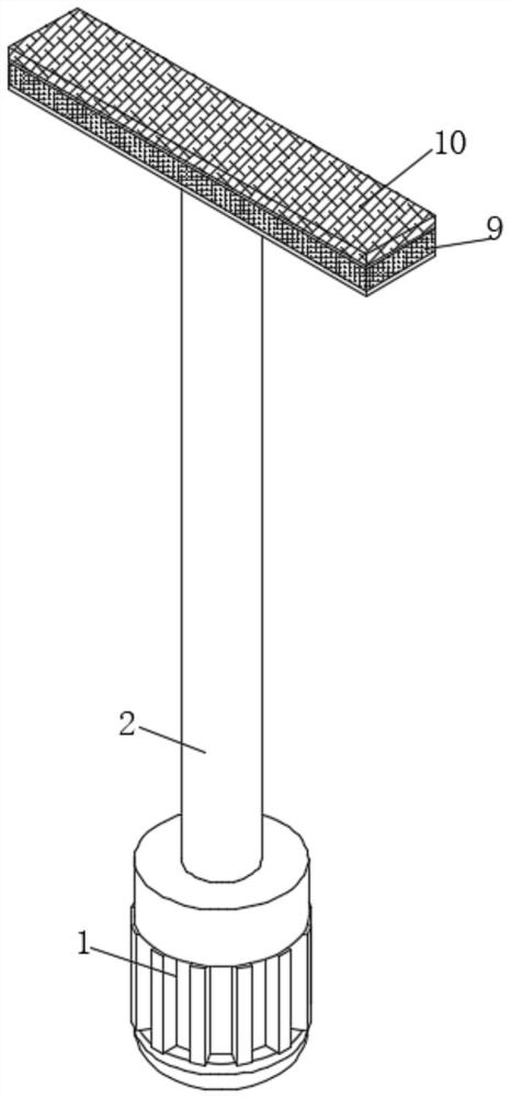
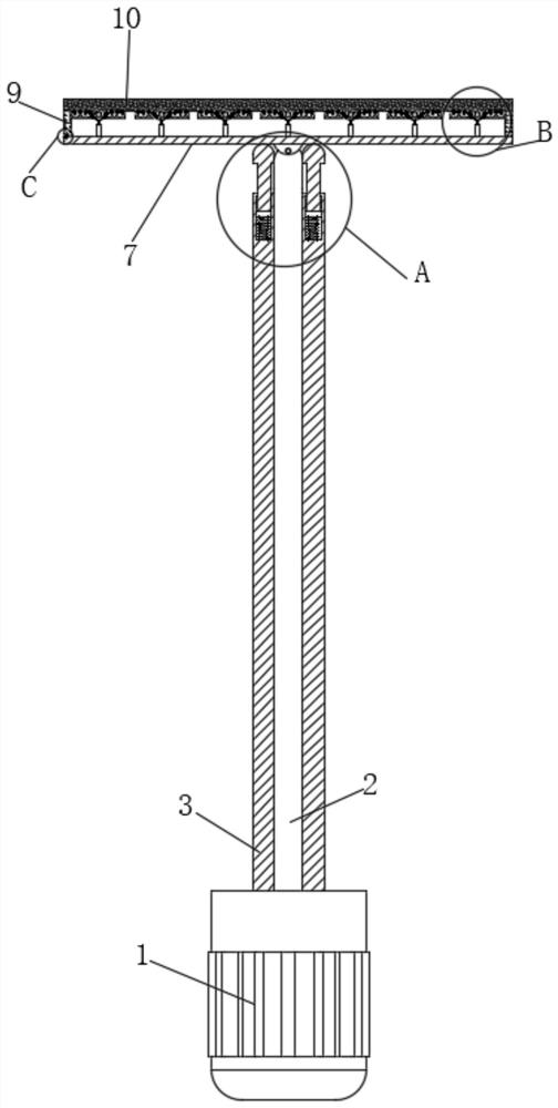
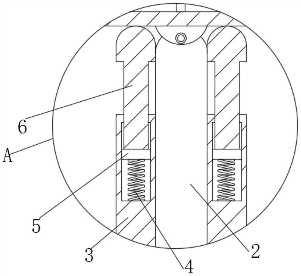
[0023] Such as Figure 1-6 As shown, the utility model provides a technical solution: a cleaning device for wind turbine blades in the wind energy industry, including a motor 1, the upper side of the motor 1 is fixedly connected with a rotating rod 2, and the upper end of the output rod of the motor 1 is fixedly connected with a The fixed cylinder 3 is plugged into the inside of the rotating rod 2. The outer wall of the rotating rod 2 does not contact the inner wall of the fixed cylinder 3. The upper end of the fixed cylinder 3 is fixedly connected with the first spring 4 at the bottom of the inner wall. The first spring 4 The upper end is fixedly connected with a connecting plate 5, the outer wall of the connecting plate 5 is slidingly connected with the inner wall of the fixed cylinder 3, the upper surface of the connecting plate 5 is fixedly connected with a support block 6, and the upper end of the support block 6 penetrates the fixed cylinder 3 and extends to the fixed cyl...


PUM


Abstract

The invention relates to the technical field of wind energy industry, and discloses a cleaning device for fan blades of a wind driven generator in wind energy industry. The cleaning device comprises a motor, wherein a rotating rod is fixedly connected to the upper side of the motor; a fixing cylinder is fixedly connected to the upper end of an output rod of the motor; the fixing cylinder is inserted into the rotating rod; a first spring is fixedly connected to the bottom of the inner wall of the upper end of the fixing cylinder; a connecting plate is fixedly connected to the upper end of the first spring; and the outer wall of the connecting plate is connected with the inner wall of the fixing cylinder in a sliding mode. During use, the elastic force of a second spring and an arc-shaped rod enables a pressing plate to slightly recover to the initial shape, cleaning sponge at the supporting position of the pressing plate can be changed along with the angle after making contact with the angle of the blade surface, the cleaning sponge can be better attached to the blade angle in cooperation with telescopic support of a spring telescopic rod to the pressing plate, and under the condition that the rotating rod is dragged to rotate, the purpose that the cleaning sponge is attached to the radian of the blade of the wind driven generator for cleaning is achieved.

Description

technical field [0001] The utility model relates to the technical field of wind energy industry, in particular to a cleaning device for fan blades of wind power generators in the wind energy industry. Background technique [0002] The windward side of the wind turbine blade (commonly known as the back of the blade) is the main source of power for the generator. The smoothness of the back of the blade is the basis for determining the speed of the fan. The width of the back of the blade itself has produced resistance in the air. If there are trachoma, cracks and damage , the resistance can be imagined, generally after two to three years of wind turbine operation, the protective gel coat on the windward side has been damaged to the peak, and the back of the blade is no longer smooth, which has a serious impact on the speed of the wind turbine and can reduce power generation by 20 %, in order to improve the utilization rate of wind power generation and reduce operating costs, th...

Claims


Application Information

Patent Timeline
Patent Type & Authority Applications(China)
IPC IPC(8): F03D80/55
CPCF03D80/55Y02E10/72
Inventor 何胜利
Owner 何胜利
Why Eureka
Try Eureka