Cover plate for new energy lithium battery and forming process of cover plate
A lithium battery and new energy technology, applied in the field of new energy lithium battery cover plate and its forming process, can solve the problem of slow exhaust efficiency and liquid injection efficiency, inability to exhaust and reduce pressure, loose terminals and positive and negative poles, etc. problems, to achieve the effect of improving liquid injection efficiency and exhaust efficiency, increasing liquid injection volume, and increasing exhaust volume
- Summary
- Abstract
- Description
- Claims
- Application Information
AI Technical Summary
Problems solved by technology
Method used
Image

Examples
Embodiment Construction
[0026] The following will clearly and completely describe the technical solutions in the embodiments of the present invention with reference to the accompanying drawings in the embodiments of the present invention. Obviously, the described embodiments are only some, not all, embodiments of the present invention.
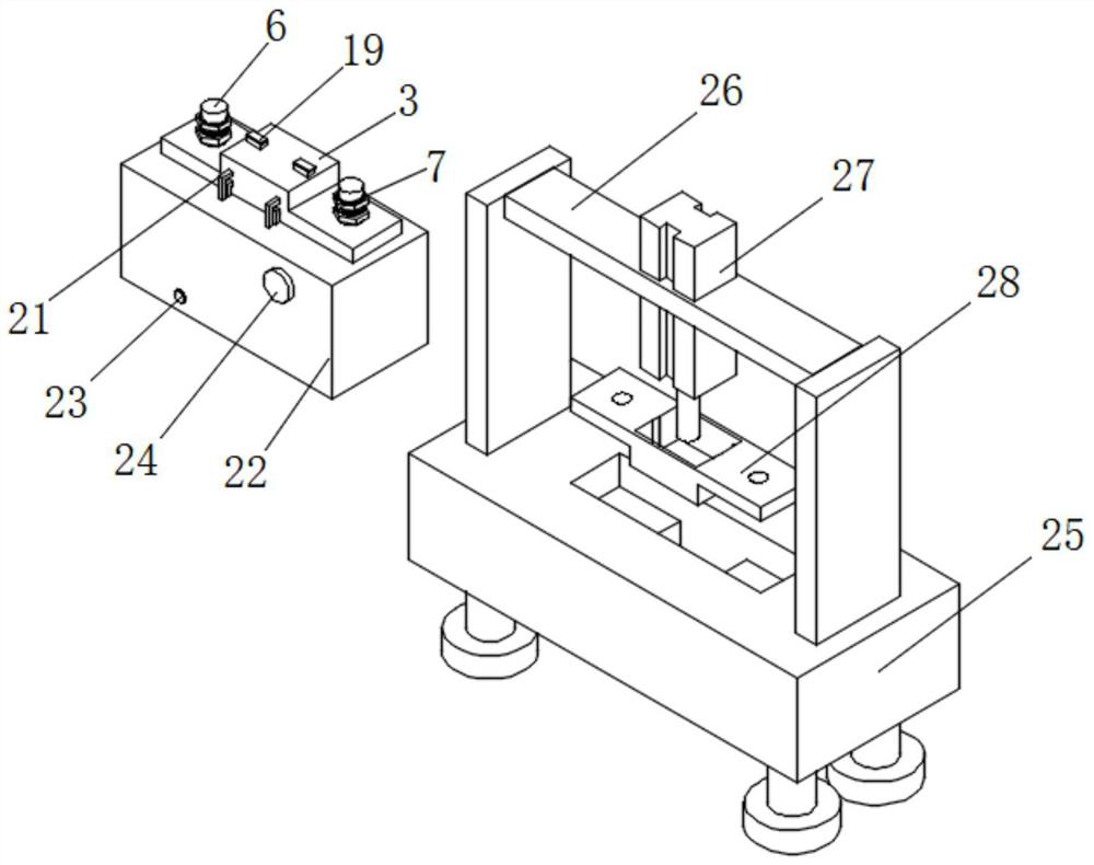
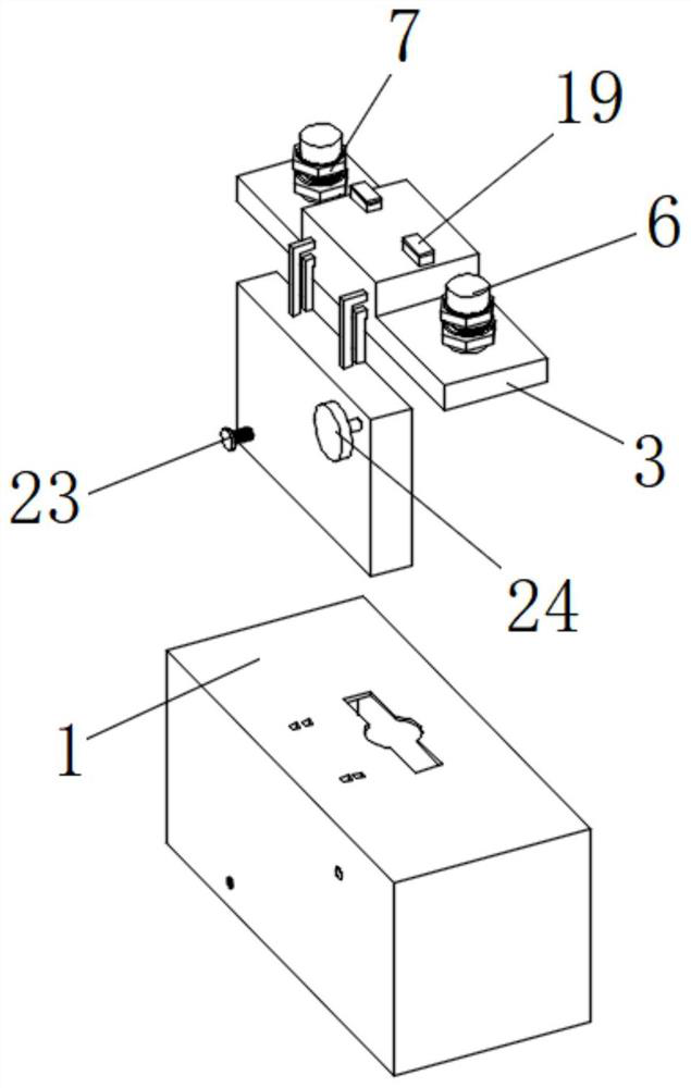
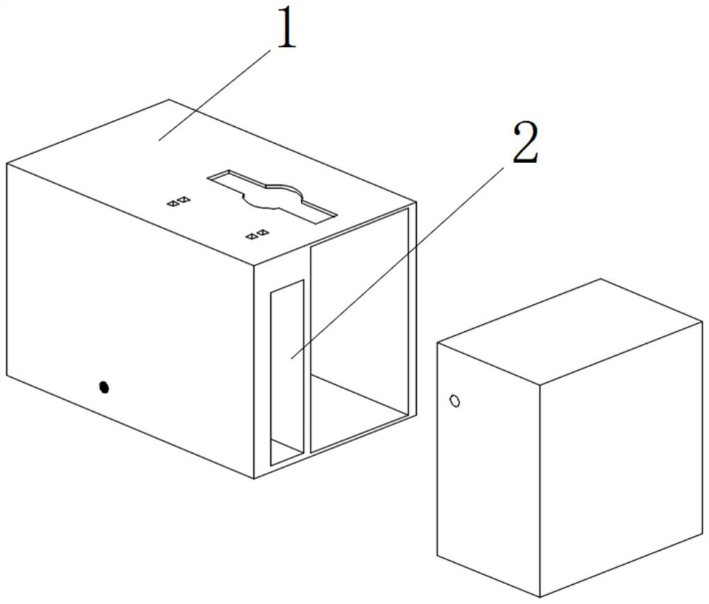
[0027] see Figure 4 with Figure 5 , the present invention provides a technical solution: a cover plate for a new energy lithium battery, including a battery box 1, a heat insulating plate 2 is arranged in the inner cavity of the battery box 1, a cover plate 3 is installed on the cover plate 3, and the cover plate The left side of the upper surface of 3 is provided with a positive electrode column 4, and the right side of the upper surface of the cover plate 3 is provided with a negative electrode column 5, and the outer surfaces of the positive electrode column 4 and the negative electrode column 5 are both equipped with a terminal fixing cover 6. The terminal fix...
PUM
 Abstract
Description
Claims
Application Information
 - Generate Ideas
- Intellectual Property
- Life Sciences
- Materials
- Tech Scout
- Unparalleled Data Quality
- Higher Quality Content
- 60% Fewer Hallucinations
Browse by: Latest US Patents, China's latest patents, Technical Efficacy Thesaurus, Application Domain, Technology Topic, Popular Technical Reports.
© 2025 PatSnap. All rights reserved.Legal|Privacy policy|Modern Slavery Act Transparency Statement|Sitemap|About US| Contact US: help@patsnap.com