Plasma source chamber for a spectrometer

A technology of plasma source and spectrometer, applied in the direction of plasma, emission spectrum, instrument, etc., can solve the problems of needing pre-cooler, expensive, complex arrangement, etc., to avoid heat transfer, prevent air flow interference, and improve thermal insulation Effect

Pending Publication Date: 2021-11-16
THERMO FISHER SCI BREMEN
View PDF1 Cites 0 Cited by
  • Summary
  • Abstract
  • Description
  • Claims
  • Application Information

AI Technical Summary

Problems solved by technology

In addition, the plasma chamber of JP2005-205296 requires a precooler, a gas cooler and a fan, making the arrangement complicated and relatively expensive

Method used


Image

  • Plasma source chamber for a spectrometer
  • Plasma source chamber for a spectrometer
  • Plasma source chamber for a spectrometer

Examples


Embodiment Construction

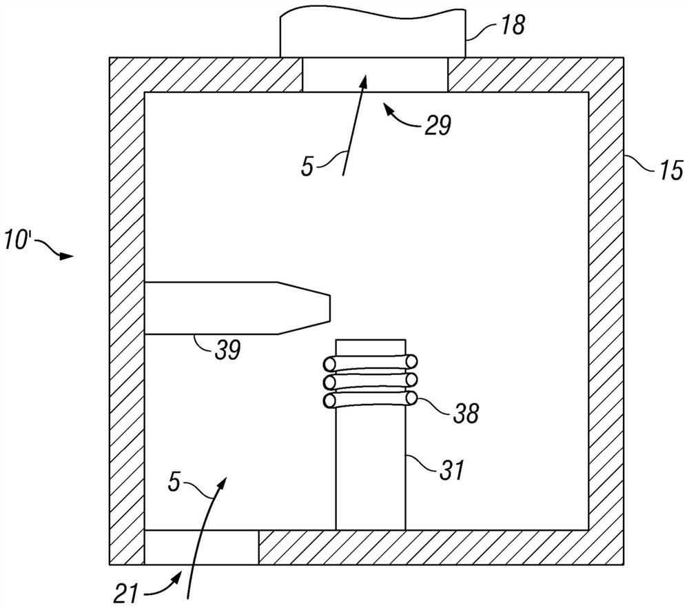
[0031] exist figure 1 A plasma chamber according to the prior art is schematically illustrated in cross-section in . Such plasma chambers (or plasma source chambers) are used, for example, by Thermo Fisher Scientific Inc. ) made iCAP 7000 TM in the mass spectrometer. The illustrated plasma chamber 10' comprises a housing 15 in which a plasma torch 31 is housed. The plasma torch 31 is provided with an RF inductive coil 38 arranged around a part of the length of the plasma torch 31 . The RF induction coil 38 serves as a heating element for generating the plasma. Viewing pieces 39 protrude from the side walls of the plasma chamber to allow side viewing of the plasma in use. The exhaust pipe 18 is arranged on the top wall of the plasma chamber 10 ′, and directly communicates with the exhaust port opening 29 located above the plasma torch 31 . A gas inlet opening 21 is provided in the bottom wall of the plasma chamber, adjacent to the side walls.

[0032] The location of th...


PUM


Abstract

A plasma source chamber (10) for use in a spectrometer comprises an inner housing (11) for accommodating a plasma source (31) and an outer housing (12) accommodating the inner housing. The outer housing (12) comprises at least one outer air inlet opening (21) in a first wall and at least one outer air outlet opening (22) in a second wall. Walls of the inner housing and walls of the outer housing define a spacing (25) so as to allow a first air flow (1) from the at least one outer air inlet opening (21) to the at least one outer air outlet opening (22) through the spacing (25) between the inner housing and the outer housing. The inner housing (11) comprises at least one inner air inlet opening (23) in a first wall and at least one inner air outlet opening (24) in a second wall to allow a second air flow (2) from the at least one inner air inlet opening to the at least one inner air outlet opening through the inner housing. Thus, an improved cooling of the outer surfaces of the plasma source chamber is achieved.

Description

technical field [0001] The invention relates to a plasma source chamber for a spectrometer. More specifically, the present invention relates to plasma source chambers for use in spectrometers that are capable of containing a plasma source without the need for active cooling elements within the chamber. Background technique [0002] It is well known to use plasma sources in spectrometers such as emission spectrometers and mass spectrometers. Plasma sources, such as inductively coupled plasma (ICP) sources, generate plasmas in which atoms and molecules can be ionized. In such plasmas, extremely high temperatures may occur, such as temperatures of 8,000K or even 10,000K. In conventional spectrometers, the plasma source is housed in a large chamber, thus allowing a relatively large distance between the plasma and the walls and other parts of the chamber. As users of spectrometers increasingly demand more compact instruments, the size of the plasma source chamber has decreased...

Claims


Application Information

Patent Timeline
Patent Type & Authority Applications(China)
IPC IPC(8): G01N21/73G01J3/443H05H1/46
CPCG01N21/73G01N2201/022H05H1/30H05H1/0037G01N21/68G01N21/71H01J37/32972H05H1/28
Inventor N·夸斯A·穆塔津S·盖斯勒T·沃尔夫J·拉斯坎普D·沃勒斯M·斯柯布林
Owner THERMO FISHER SCI BREMEN
Why Eureka
Try Eureka