Processing device for concave structures on surface of metal pipe

A technology for metal pipes and processing devices, applied in metal processing equipment, feeding devices, positioning devices, etc., can solve problems affecting the dimensional accuracy and shape accuracy of workpieces, difficulty in ensuring processing accuracy and product quality, and deformation of metal pipes under compression , to achieve the effect of ensuring machining accuracy, reducing labor intensity and manual operation error rate, and improving stability

Active Publication Date: 2021-11-19
南通市力行机械制造有限公司
View PDF9 Cites 3 Cited by
  • Summary
  • Abstract
  • Description
  • Claims
  • Application Information

AI Technical Summary

Problems solved by technology

[0003] The existing metal pipe surface concave structure processing device has the following deficiencies: 1. During processing, the vibration generated by the operation of the equipment can easily cause the bending of the metal pipe, thereby affecting its processing accuracy and reducing product quality; 2. , Because the metal pipe wall is thin, if the clamping force of the fastener is large, it is easy to cause the metal pipe to deform under pressure, thereby affecting the dimensional accuracy and shape accuracy of the workpiece. If the clamping force is reduced, the workpiece may be processed 3. In order to ensure that the processed concave structure is evenly arranged on the surface of the metal pipe, the staff needs to manually rotate the metal pipe to achieve different positions in the circumferential direction of the metal pipe. Processing is labor-intensive, and manual operation errors exist, making it difficult to guarantee processing accuracy and product quality; 4. During work, the speed of axial movement of the metal pipe and the punching frequency of the punch need to be manually adjusted, the operation is complicated, and the processing efficiency is low

Method used


Image

  • Processing device for concave structures on surface of metal pipe
  • Processing device for concave structures on surface of metal pipe
  • Processing device for concave structures on surface of metal pipe

Examples


Embodiment Construction

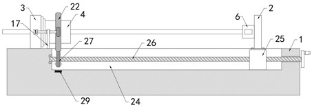
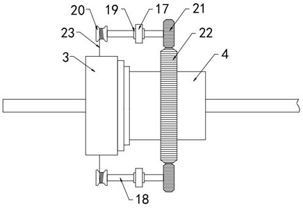
[0028] Such as Figure 1-6 As shown, a processing device for a concave structure on the surface of metal pipes includes a frame 1, on which a mounting plate 2 is slidably arranged, and a fastening mechanism for fixing metal pipes is rotatably provided on the mounting plate 2, the machine A die seat 3 is fixedly arranged on the frame 1, and the middle part of the die seat 3 is provided with a through hole for metal pipe processing. The die seat 3 is provided with multiple sets of die mechanisms for carrying out concave processing of the metal pipe. The side of the die seat 3 A twisting cylinder 4 is rotatably connected to the wall, and the axis of the twisting cylinder 4 is in line with the axis of the through hole. Several conveying rollers 5 are arranged inside the twisting cylinder 4 .

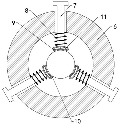
[0029] The fastening mechanism includes a fixed cylinder 6 and multiple sets of clamping parts. In this embodiment, there are three sets of clamping parts, which can ensure that the surface ...


PUM


Abstract

The invention belongs to the technical field of metal pipe surface processing, and particularly relates to a processing device for concave structures on the surface of a metal pipe. The processing device comprises a rack, wherein a mounting plate is arranged on the rack in a sliding manner; a fastening mechanism for fixing the metal pipe is rotatably arranged on the mounting plate; a stamping die base is fixedly arranged on the rack; a through hole used for processing the metal pipe is formed in the middle of the stamping die base; a plurality of stamping die mechanisms used for conducting concave surface processing on the metal pipe are arranged in the stamping die base; and a torsion cylinder is rotationally connected to the side wall of the stamping die base, and the axis of the torsion cylinder and the axis of the through hole are collinear. In the concave surface processing process of a punch, the metal pipe can be driven to intermittently rotate and axially move, automatic adjustment of the processing position is achieved, so that the processed concave structures are evenly distributed, and the product quality is improved; and through the arrangement of a compression spring and an electromagnet, the fastening effect on the metal pipe is good, and the stability of equipment during working is improved.

Description

technical field [0001] The invention belongs to the technical field of surface processing of metal pipes, in particular to a processing device for concave structures on the surface of metal pipes. Background technique [0002] Heat pipe is one of the widely used and very effective heat transfer components. It mainly achieves the purpose of heat dissipation through the flow of cooling medium such as heat transfer oil in the pipe. When the existing heat pipe is produced and processed, it will process concave holes on the pipe wall. Shaped structure to increase its contact surface area, the regularly arranged concave shape can also increase the flow rate of cooling oil, greatly improving the heat dissipation performance of the heat pipe. [0003] The existing metal pipe surface concave structure processing device has the following deficiencies: 1. During processing, the vibration generated by the operation of the equipment can easily cause the bending of the metal pipe, thereby...

Claims


Application Information

Patent Timeline
Patent Type & Authority Applications(China)
IPC IPC(8): B21D22/04B21D43/00B21D43/14B21D53/06
CPCB21D22/04B21D22/025B21D43/003B21D43/145B21D53/06
Inventor 季栋梁
Owner 南通市力行机械制造有限公司
Why Eureka
Try Eureka