
Polishing device adopting high-strength wear-resistant diamond abrasive belt

A diamond sand and polishing device technology, which is applied in the direction of grinding/polishing safety device, grinding drive device, grinding/polishing equipment, etc., can solve the problem of limited contact area between polishing abrasive belt and arc-shaped workpiece surface and time-consuming polishing operation Power consumption, large size and difficult to carry, etc., to achieve the effect of being convenient for close contact with workpiece polishing, easy to disassemble and replace, and preventing the operation from being affected

Pending Publication Date: 2021-11-19
盐城市锐克斯研磨科技有限公司
View PDF0 Cites 2 Cited by
  • Summary
  • Abstract
  • Description
  • Claims
  • Application Information

AI Technical Summary

Problems solved by technology

[0005] The object of the present invention is to provide a kind of polishing device that adopts high-strength wear-resistant diamond abrasive belt, to solve the polishing device of existing high-strength wear-resistant diamond abrasive belt proposed in the above-mentioned background technology, in the process of its use, The size is too large and not easy to carry. The surface contact area between the polishing abrasive belt and the arc-shaped workpiece is limited, which makes the polishing operation time-consuming and labor-intensive. The generated waste chips fly around the device, which interferes with the operation.

Method used


Image

  • Polishing device adopting high-strength wear-resistant diamond abrasive belt
  • Polishing device adopting high-strength wear-resistant diamond abrasive belt
  • Polishing device adopting high-strength wear-resistant diamond abrasive belt

Examples


Embodiment 1

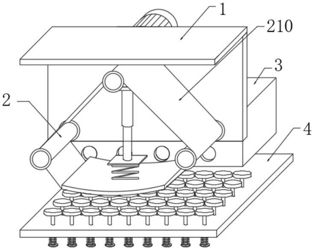
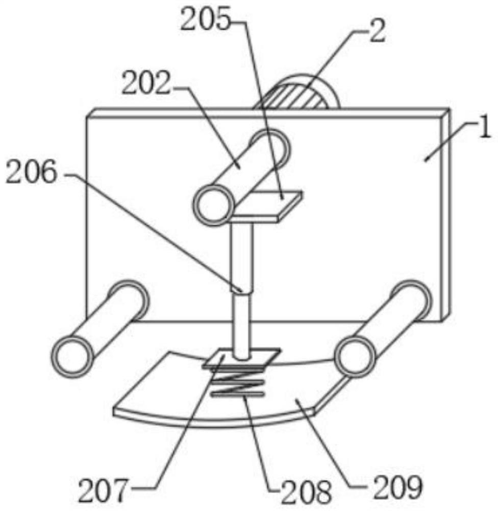
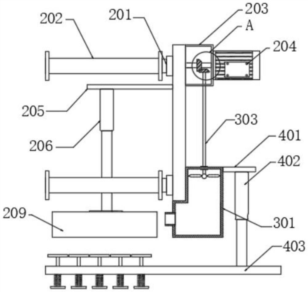
[0029] See 1- image 3 , in the embodiment of the present invention, the polishing assembly 2 includes: three first bearings 201 fixed on the front surface of the outer shell 1, the rotating ends of the three first bearings 201 are fixed with a rotating roller 202, and the surfaces of the three rotating rollers 202 are sleeved with Abrasive belt 210; the mounting frame 203 fixed on the rear end surface of the outer shell 1, the drive motor 204 is installed inside the mounting frame 203; The first cylinder 206, the output end of the first cylinder 206 is fixed with a connecting plate 207, the lower end of the connecting plate 207 is fixed with a first spring 208, the lower end of the first spring 208 is fixed with an arc plate 209, and the output end of the drive motor 204 passes through the outer shell 1. The first bearing 201 is fixedly connected with the rotary roller 202, used for the rotation of the rotary roller 202 and the abrasive belt 210, and the arc plate 209 is mova...

Embodiment 2

[0031] see Figure 3-Figure 5 The difference from Embodiment 1 is that the blower assembly 3 includes: a bellows 301 fixed on the rear end surface of the outer casing 1, the upper end of the bellows 301 is fitted with a second bearing 302, and the rotating end of the second bearing 302 is fixed with a transmission rod 303 , the extended end of the transmission rod 303 lower end is fixed with the blower fan 305 arranged in the inner cavity of the bellows 301; the pair of bevel gears 304 between the upper end of the transmission rod 303 and the output end of the drive motor 204 are fixed; An air exhaust port 306, the air exhaust port 306 is arranged opposite to the bottom of the abrasive belt 210, and is used to blow the abrasive belt 210 to polish the scattered gravel. When the output end of the driving motor 204 rotates, the transmission rod 303 can be driven to rotate by the pair of bevel gears 304 , the transmission rod 303 can drive the blower fan 305 to rotate, so that the...

Embodiment 3

[0033] see image 3 and Figure 6The difference from Embodiment 1 is that the extrusion assembly 4 includes: a second horizontal plate 401 fixed on the rear end surface of the bellows 301, a second cylinder 402 is fixed on the lower end of the second horizontal plate 401, and a set is fixed on the lower end of the second cylinder 402. The supporting plate 403 below the abrasive belt 210; and several ejector pins 404 that penetrate through the supporting plate 403, and the upper end surface of the ejector bar 404 is fixed with a tray 406, and the first pin is fixed between the ejector bar 404 and the lower end surface of the supporting plate 403 Two springs 405, the supporting plate 403 are arranged opposite to the lower end of the arc-shaped plate 209, and are used to squeeze the polishing piece to the surface of the arc-shaped plate 209, and several trays 406 move up and down in the socketed supporting plate 403 through the push rod 404, Therefore, several pallets 406 can mo...


PUM


Abstract

The invention discloses a polishing device adopting a high-strength wear-resistant diamond abrasive belt. The polishing device comprises an outer shell; a polishing assembly is arranged on the front end face of the outer shell and used for polishing workpieces with different radians; and an air blowing assembly is arranged on the rear end face of the outer shell and used for blowing and cleaning scraps generated during polishing operation. According to the polishing device, an arc-shaped plate can be driven to ascend and descend through a first air cylinder, so that the lower end of the abrasive belt can be extruded to be in an arc-shaped protrusion shape, the contact area between the polishing device and an arc-shaped workpiece can be increased through the abrasive belt at the arc-shaped protrusion, the polishing efficiency is improved, the abrasive belt is easy to disassemble and replace, while a driving motor drives the abrasive belt to rotate, the driving motor can also drive a blower fan to rotate, so as to blow away the scraps during the operation, the operation is prevent from affecting, a plurality of trays can be lifted and moved, so that the arc-shaped workpiece can be tightly lifted at the lower end of the abrasive belt, the abrasive belt is convenient to be in tight contact with the workpiece for polishing, and the device is small in size and easy to carry.

Description

technical field [0001] The invention relates to the field of abrasive belt polishing equipment, in particular to a polishing device using a high-strength and wear-resistant diamond abrasive belt. Background technique [0002] Abrasive belts are coated abrasives, called flexible abrasives, which are more flexible and safer than solid abrasive grinding wheels during polishing, with higher precision and low grinding costs. Hard material synthetic diamond abrasive grains, coated abrasives adhered to flexible and bendable substrates, that is, emery cloth or sandpaper, are often used for polishing the surface of workpieces. [0003] The existing high-strength and wear-resistant diamond abrasive belt polishing device is too large and difficult to carry during its use, and the surface contact area between the polishing abrasive belt and the arc-shaped workpiece is limited, which makes the polishing operation time-consuming and labor-intensive. The generated waste flies around the d...

Claims


Application Information

Patent Timeline
Patent Type & Authority Applications(China)
IPC IPC(8): B24B21/00B24B21/18B24B21/20B24B41/06B24B47/22B24B55/08
CPCB24B21/00B24B21/18B24B21/20B24B55/08B24B41/06B24B47/22
Inventor 王志成
Owner 盐城市锐克斯研磨科技有限公司
Learn More