
Cam grinding clamp for camshaft

A technology of camshafts and fixtures, which is applied in the direction of grinding workpiece supports, etc., can solve the problems of cam grinding phase angle error, diameter mismatch, high procurement cost, etc., and achieve the effects of ensuring machining accuracy, not easy to wear, and reducing production costs

Pending Publication Date: 2021-11-19
JIANGXI TONGXIN MACHINERY MFG
View PDF0 Cites 0 Cited by
  • Summary
  • Abstract
  • Description
  • Claims
  • Application Information

AI Technical Summary

Problems solved by technology

[0002] At present, there are two ways of clamping the camshaft when grinding the cam: automatic clamping and manual clamping. The automatic clamping can meet the needs of the clamping and positioning of the camshaft and cam grinding, but it needs to customize the spring chuck and positioning mechanism, which can only be used It is limited to single product processing, and the procurement cost is high and the cycle is long; the manual clamping method is to manually install the cam grinding fixture on the camshaft. This way makes the keyway on the end face of the camshaft correspond to the positioning key through manual rotation. The positioning key is embedded in the keyway, but because the diameter of the clamp does not correspond to the diameter of the outer circle of the end face of the camshaft, the size of the clamping outer circle directly affects the phase angle error of the cam grinder

Method used


Image

  • Cam grinding clamp for camshaft

Examples


Embodiment Construction

[0012] The grinding cam clamp of the camshaft of the present invention will be further detailed below with reference to the accompanying drawings.

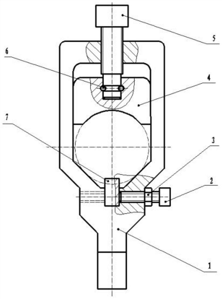
[0013] figure 1 The grinding cage clamp of the camshaft, including the clamp body 1 and the block 4, the clamp body 1 is provided with a rectangular parallelepiped, the upper portion of the clamp body 1 is hollowed, the upper portion of the clamp body 1 is a rectangular cavity, and the lower portion of the clamp body 1 is tapered The cavity, the upper end of the upper end of the rectangular cavity is provided with a screw hole, and the block 4 is provided in the rectangular cavity, and the upper portion of the block 4 is disposed at the lower end of the clamping screw, the lower end of the clamping screw 5 passes through the clamp body 1 In the groove in the upper portion of the pressure block 4, the side surface of the diaphragm 4 recess is provided, and the cylindrical pin is placed in the side through hole of the groove of the gro...


PUM


Abstract

The invention discloses a cam grinding clamp for a camshaft. The clamp comprises a clamp body (1) and a pressing block (4), the clamp body (1) is a cuboid, the middle of the clamp body (1) is hollowed out to form a cavity, the upper portion of the clamp body (1) is a rectangular cavity, the lower portion of the clamp body (1) is a conical cavity, a screw hole is formed at the position, at the upper end of the rectangular cavity, of the middle of the clamp body (1), and the pressing block (4) is arranged in the rectangular cavity. A groove is formed at the position, corresponding to the lower end of a clamping screw (5), of the upper portion of the pressing block (4), the lower end of the clamping screw (5) penetrates through the screw hole in the middle of the clamp body (1) to be arranged in the groove at the upper portion of the pressing block (4), a through hole is formed in the side face of the groove of the pressing block (4), a cylindrical pin is arranged in the through hole in the side face of the groove of the pressing block (4), and the bottom of the pressing block (4) is in an arc shape. A key groove is formed at the conical position of a conical cavity, a positioning key (7) corresponds to the key groove at the conical position and is arranged in the key groove, a screw hole is formed in the side face of the key groove at the conical position, and the positioning key (7) is fixed in the key groove at the conical position through an inner hexagon screw (2) and a hexagon nut (3), so that cam grinding does not generate phase angle errors.

Description

Technical field [0001] The present invention relates to a grinding clamp of a cam shaft, specifically a clamp for cam grinding. Background technique [0002] At present, the cam axle clip has two types of automatic assembly and handmade clamp. The automatic assembly can meet the needs of the camshaft cam grinding clip, but it is necessary to customize the spring collet and positioning mechanism. In a single product processing, high procurement cost, long period of cycle; the manual handle is used in manual way to hold the cam grinding clamp on the camshaft, in which the cam shaft end face groove corresponds to the positioning key, The positioning button embeds into the key slot, but since the jig diameter is not corresponding to the outer diameter of the cam shaft end surface, the size of the outer circle directly affects the phase angle error of the cam mill. Inventive content [0003] The object of the present invention is intended to provide a grinding clamp of a cam shaft, o...

Claims


Application Information

Patent Timeline
Patent Type & Authority Applications(China)
IPC IPC(8): B24B41/06
CPCB24B41/06
Inventor 朱振滔杨启明余天纪金强徐道广俞协余巧程志生王刚
Owner JIANGXI TONGXIN MACHINERY MFG
Learn More