FAC mirror assembling and adjusting system and assembling and method

A technology for adjusting and collimating lenses, which is applied in the direction of installation and surface coating of liquid devices, instruments, etc., can solve the problems of position error, light spot position directivity deviation, light spot deviation up and down, left and right heights, etc., to improve the installation The effects of adjusting accuracy, enhancing directivity, and improving adjustment accuracy and efficiency

Active Publication Date: 2021-11-19
BWT BEIJING
View PDF6 Cites 4 Cited by
  • Summary
  • Abstract
  • Description
  • Claims
  • Application Information

AI Technical Summary

Problems solved by technology

[0003] In the prior art, a purely manual FAC mirror operation platform is used for the installation and adjustment of the FAC mirror. In the process of installing and adjusting the tray and the FAC mirror, the manual FAC mirror operation platform is prone to position errors, resulting in the up and down shift of the light spot and the left and right High and low offset, so that in the process of mass order production, the consistency of pallet and FAC mirror adjustment cannot be achieved
In addition, in the process of manually adjusting the position of the FAC mirror, the position of the spot is directly recognized by the human eye. In this way, in the process of mass order production, the direct recognition of the spot by the human eye will lead to a deviation in the position and directivity of the spot, and the efficiency of the human eye to recognize the spot Low, not suitable for high-precision assembly and adjustment of FAC mirrors in large quantities

Method used


Image

  • FAC mirror assembling and adjusting system and assembling and method
  • FAC mirror assembling and adjusting system and assembling and method
  • FAC mirror assembling and adjusting system and assembling and method

Examples


Embodiment Construction

[0032] In order to make the purpose, technical solution and advantages of the present invention clearer, the technical solution of the present invention will be clearly and completely described below in conjunction with specific embodiments of the present invention and corresponding drawings. Apparently, the described embodiments are only some of the embodiments of the present invention, but not all of them. Based on the embodiments of the present invention, all other embodiments obtained by persons of ordinary skill in the art without making creative efforts belong to the protection scope of the present invention.

[0033] The technical solutions provided by various embodiments of the present invention will be described in detail below in conjunction with the accompanying drawings.

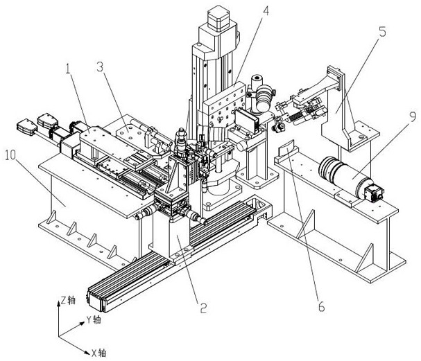
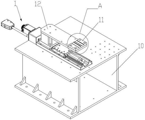
[0034] to combine Figure 1 to Figure 9 As shown, the FAC mirror assembly system of this embodiment includes a material component 1 , a transfer component 2 , a dispensing component 3 , a laser ...


PUM


Abstract

The invention discloses an FAC mirror assembling and adjusting system and method. The FAC mirror assembling and adjusting system comprises a material assembly, a transfer assembly, a dispensing assembly, a laser assembly, a curing assembly, a collimating lens and a CCD camera. The material assembly is used for placing a tray and an FAC mirror, and the transfer assembly is used for transferring the tray and the FAC mirror; the curing assembly is used for curing the glue solution of the tray and the glue solution of the FAC mirror, so that the tray is connected with a heat sink in the laser assembly through glue solution curing, and the FAC mirror is connected with the tray through glue solution curing; and the collimating lens is used for collimating light beams emitted by the bar to form light spots, the light spots are mapped on the CCD camera, the CCD camera further displays the deviation direction and the deviation distance of the light spots relative to the light-emitting central axis of the bar, and the transfer assembly adjusts the FAC mirror according to the deviation direction and the deviation distance. According to the FAC mirror assembling and adjusting device, automatic transferring and assembling and adjusting operation of the tray and the FAC mirror are achieved, so that manual assembling and adjusting operation is replaced, and the assembling and adjusting precision and efficiency of the FAC mirror are improved.

Description

technical field [0001] The invention belongs to the technical field of semiconductor lasers, and in particular relates to an assembly and adjustment system and an assembly method of an FAC mirror. Background technique [0002] The FAC (Fast Axis Collimator optical component-fast axis collimator) mirror of the laser bar has directivity to the light path of the light output, and the directivity of the light path is the directionality of the light path. The divergence angle is used as the basis for evaluating the divergence of the light path. The divergence angle The meaning is: within the angle of the divergence angle, there is a light path that exits. When the emission angle approaches zero, the beam can be approximately called "parallel light". The position of the FAC mirror affects the divergence angle of the laser beam and the uniformity of the laser spot, so the position of the FAC mirror of the laser bar is the basis of the entire optical path, affecting such as slow axi...

Claims


Application Information

Patent Timeline
Patent Type & Authority Applications(China)
IPC IPC(8): G02B7/00B05C5/02B05C13/02B05C9/12B05D3/06
CPCG02B7/00B05C5/0208B05C13/02B05C9/12B05D3/067
Inventor 陈晓华陈瑞雪于振坤王江云赵帆罗校迎
Owner BWT BEIJING
Why Eureka
Try Eureka