Supercharge Your Innovation With Domain-Expert AI Agents!

Driving circuit, driving method and microfluidic substrate

A technology of driving circuit and driving method, which is applied in the field of microfluidics, and can solve problems such as dielectric layer charging accumulation, affecting chip performance and application, frequency frame frequency limitation, etc.

Active Publication Date: 2021-11-19
SHANGHAI TIANMA MICRO ELECTRONICS CO LTD
View PDF9 Cites 0 Cited by
  • Summary
  • Abstract
  • Description
  • Claims
  • Application Information

AI Technical Summary

Problems solved by technology

In the passive driving scheme, the driving electrode is directly connected to the signal, and it can be driven by an AC signal or a DC signal. For passive driving, if a DC signal is used for driving, the dielectric layer will be charged and accumulated, which will easily lead to hysteresis and residual droplets. The driving ability of biochemical reagents is weak, which affects the performance and application of the chip; if the AC signal is used for passive driving, the number of signals required is large, that is, more signal lines are required to transmit signals, which will increase the difficulty of production and cost
[0005]So the existing technology is more and more inclined to the development of active driving scheme, and for the general active driving scheme of 1T1C, the signal on the driving electrode depends on the storage Capacitor retention, unable to achieve AC output within one frame time; even if the positive and negative voltages are provided in different frames to provide an AC-like effect, but its frequency is limited by the frame frequency, which cannot meet the needs of digital microfluidics (usually 0.1 ~100kHz, preferably 1-10kHz)

Method used


Image

  • Driving circuit, driving method and microfluidic substrate
  • Driving circuit, driving method and microfluidic substrate
  • Driving circuit, driving method and microfluidic substrate

Examples


Embodiment Construction

[0044] Various exemplary embodiments of the present invention will now be described in detail with reference to the accompanying drawings. It should be noted: Unless specifically stated otherwise, the relative arrangement of the components and steps otherwise set forth in these embodiments, the numerical expressions and numerical values ​​are not limiting the scope of the present invention.

[0045] Following description of exemplary embodiments of at least one embodiment is merely illustrative, and not as any limitation on the present invention and its application, or uses.

[0046]In the relevant art known to those skilled in the art, methods and devices may not be discussed in detail, but in appropriate cases, the techniques, methods and apparatus are to be considered as part of the specification.

[0047] In all of the examples illustrated and discussed herein any specific values ​​should be construed as merely illustrative, and not by way of limitation. Thus, other examples o...


PUM


Abstract

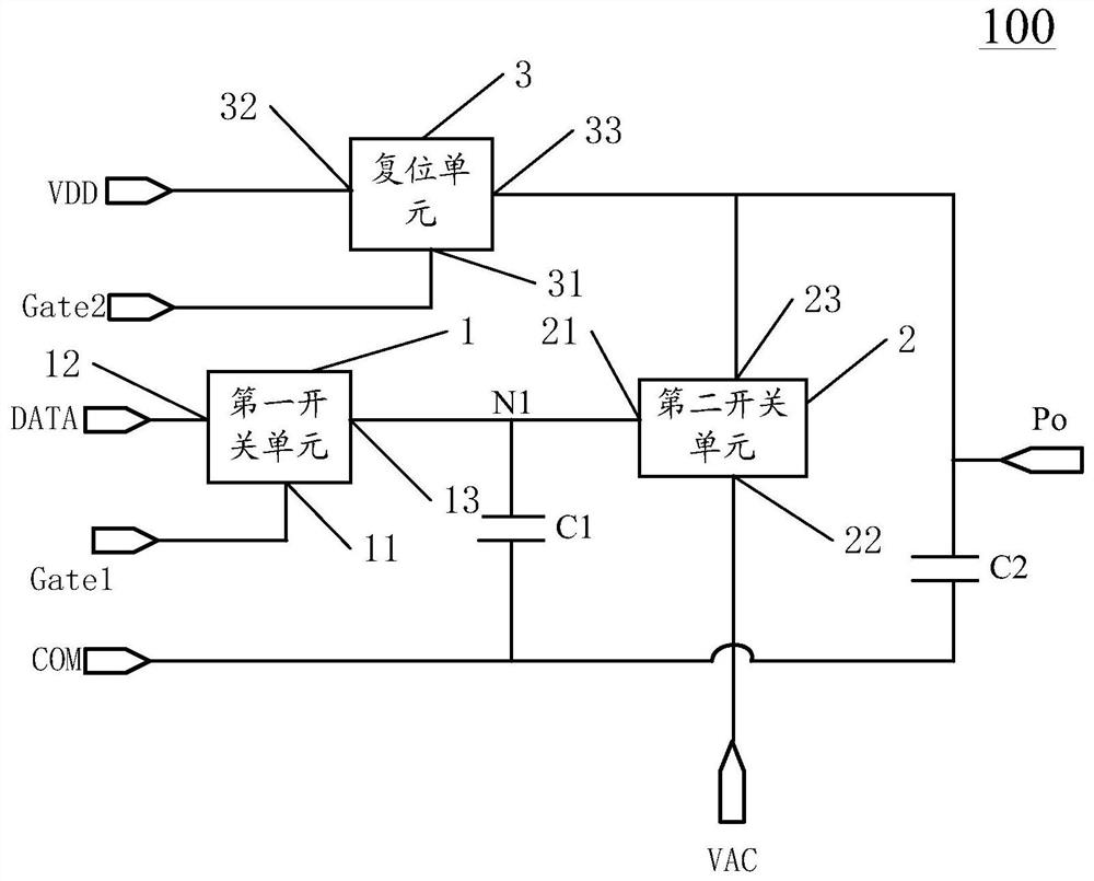
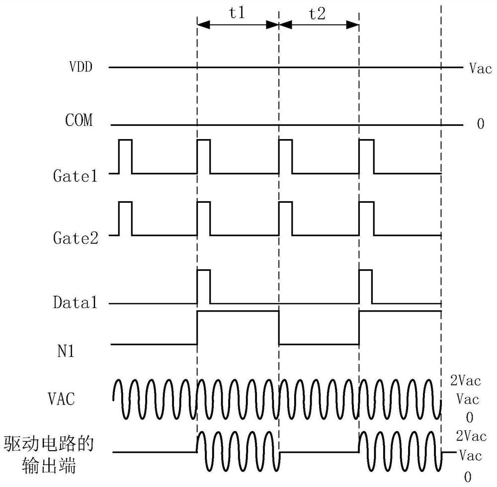
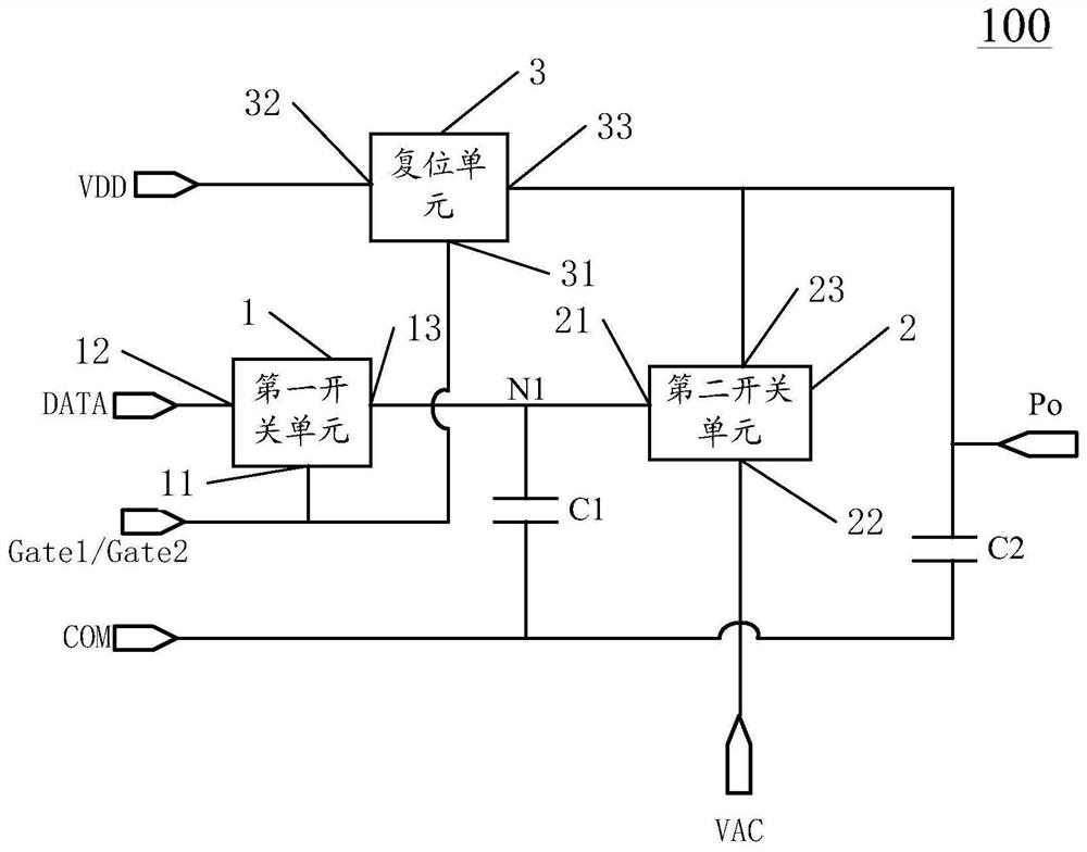
The invention discloses a driving circuit, a driving method and a microfluidic substrate. The driving circuit comprises a first switch unit, a second switch unit, a reset unit, a first capacitor and a second capacitor, wherein the driving process comprises a first stage and a second stage, the first switch unit is switched on in the first stage, a first voltage signal is transmitted to a first node, the second switch unit is switched on, a second voltage signal is input to the output end of the driving circuit, the driving circuit outputs an alternating-current signal, and the alternating-current signal output time is maintained after the first capacitor is charged; and in a second stage, the first switch unit is switched off, meanwhile, an effective signal output by a second scanning signal end controls the reset unit to be switched on, a third voltage signal is input to the output end of the driving circuit for resetting, the driving circuit outputs a direct-current signal, and the direct-current signal output time is maintained after the second capacitor is charged. According to the driving circuit the output end of the driving circuit is switched between a high-frequency alternating-current signal and a direct-current signal, the hysteresis residual problem of the microfluidic substrate is solved, and the driving performance is enhanced.

Description

Technical field [0001] The present invention relates to the field of microfluidic control technology, and more particularly, relates to a circuit for a microfluidic substrate and a driving method. Background technique [0002] Microfluidic (a Microfluidics) technology refers to the use of micro-channels (the size of several tens to hundreds of microns) for a minute or manipulating the fluid (A nanoliter volume liters) technique. Microfluidic technology can be applied to the field of genetic engineering, disease diagnosis and drug discovery, cell analysis, environmental monitoring and protection, health quarantine, forensic and so on. [0003] In the field of digital control technology based on electrical microfluidic wetting (EWOD, electrowetting-on-dielectric), the microfluidic circuit board commonly used to control a voltage drive electrode, so that an electric field is formed between adjacent drive voltage, the droplets mobile driven by an electric field. [0004] Currently, i...

Claims


Application Information

Patent Timeline
Patent Type & Authority Applications(China)
IPC IPC(8): G09G3/34
CPCG09G3/348G09G2310/061G09G2380/08G09G2300/0852G09G2230/00G09G2310/0208G09G2320/0204B01L3/502792G02B26/005B01L3/50273B01L2300/0819B01L2400/0427
Inventor 章凯迪林柏全李伟白云飞席克瑞秦锋
Owner SHANGHAI TIANMA MICRO ELECTRONICS CO LTD
Features
  • R&D
  • Intellectual Property
  • Life Sciences
  • Materials
  • Tech Scout
  • Unparalleled Data Quality
  • Higher Quality Content
  • 60% Fewer Hallucinations
Learn More