Fuel cell cooling circulation system

A circulation system and fuel cell technology, applied in fuel cells, fuel cell additives, fuel cell heat exchange, etc., can solve problems such as increased water pump power, unfavorable integration settings, and increased stack inlet pressure to ensure safety and service life, is conducive to integrated layout, and increases the effect of net output power

Pending Publication Date: 2021-11-19
上海澄朴科技有限公司
View PDF1 Cites 0 Cited by
  • Summary
  • Abstract
  • Description
  • Claims
  • Application Information

AI Technical Summary

Problems solved by technology

However, the configuration of a water pump with a large head will cause the following problems: the power of the water pump increases, resulting in a decrease in the net output power of the entire fuel cell system; the cost of a water pump with a large head is high, which will increase the production cost of the fuel cell; There are fewer optional models, which makes it difficult to match the fuel cell system
The advantages of this system are low energy consumption, good pressure control stability, etc., but there are still deficiencies in practical application: after the compressed air is passed into the expansion tank, the expansion tank has a certain pressure, when the air compressor stops running or the air When the pressure of the expansion tank is lower than the pressure of the expansion tank, the water and gas in the expansion tank will be poured into the air circuit, which will affect the life of the fuel cell; the compressed air will enter the expansion tank through the air pipe, and with the increase of the power of the stack, the inlet of the stack ( The pressure at the outlet of the air compressor will also increase significantly, and it is necessary to install a pressure regulator on the air pipe to adjust the air pressure, which leads to a higher cost of the fuel cell system, and occupies a certain volume and space, which is not conducive to integrated installation

Method used


Image

  • Fuel cell cooling circulation system
  • Fuel cell cooling circulation system
  • Fuel cell cooling circulation system

Examples


Embodiment 1

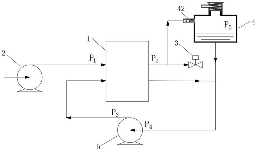
[0033] A fuel cell cooling cycle system, such as figure 1 As shown, including stack 1, air circuit, cooling circuit and pressure circuit;

[0034] The air circuit includes an air compressor 2. The air compressor 2 is used to compress the air. The compressed air passes into the stack 1 from the air inlet of the cathode of the stack 1, and the compressed air in the stack 1 comes from the air outlet of the cathode of the stack 1. Discharge the stack 1; in order to ensure the normal operation of the fuel cell, the air circuit also includes a filter, an intercooler and a humidifier. The filter is arranged upstream of the air compressor 2 for filtering air. Between the machine 2 and the stack 1, the compressed high-temperature air is cooled, and the humidifier is installed between the intercooler and the stack 1 to humidify the air, and the humidified air passes into the stack 1.

[0035] The air circuit also includes an intake pipe and an exhaust pipe. The air intake pipe connects...


PUM


Abstract

The invention relates to a fuel cell cooling circulation system which comprises an electric pile, an air loop, a cooling loop and a pressure loop, wherein the air loop comprises an air compressor, and air compressed by the air compressor is introduced into the electric pile from an air inlet of the electric pile and is discharged out of the electric pile from an air outlet of the electric pile; the cooling loop comprises an expansion water tank and a water pump, cooling liquid is introduced into the electric pile under the action of the water pump and flows back to a water inlet of the water pump from the electric pile, and the expansion water tank supplements the cooling liquid for the cooling loop; the pressure loop comprises an air delivery pipe and a one-way valve, the air delivery pipe is connected with the air outlet of the electric pile and the expansion water tank, and the one-way valve is arranged between the air outlet of the electric pile and the expansion water tank. Compared with the prior art, the gas with certain pressure at the air outlet of the electric pile is introduced into the expansion water tank, so that the requirement of the fuel cell on the lift of the water pump is reduced, the cost of the fuel cell is reduced, and the power of the water pump with smaller lift is also smaller, so that the net output power of the system of the fuel cell is increased.

Description

technical field [0001] The invention relates to the technical field of fuel cells, in particular to a fuel cell cooling circulation system. Background technique [0002] In a fuel cell system, in order to ensure that the stack can operate in a relatively ideal state, it is generally required to maintain a certain pressure difference between the cooling side of the stack and the anode and cathode of the stack, so as to avoid the Excessive cathode pressure difference leads to interpenetration of hydrogen, air, and coolant. [0003] At present, the power of the fuel cell system is getting bigger and bigger. In order to ensure the pressure on the cooling side, it is necessary to configure a water pump with a relatively large lift. However, the configuration of a water pump with a large head will cause the following problems: the power of the water pump increases, resulting in a decrease in the net output power of the entire fuel cell system; the cost of a water pump with a larg...

Claims


Application Information

Patent Timeline
Patent Type & Authority Applications(China)
IPC IPC(8): H01M8/04007H01M8/04014H01M8/04029
CPCH01M8/04029H01M8/04014H01M8/04067Y02E60/50
Inventor 马天才
Owner 上海澄朴科技有限公司
Why Eureka
Try Eureka