Surface flow wetland purification device

A purification device and wetland technology, applied in chemical instruments and methods, plant support, horticulture, etc., can solve the problems of easy dumping of plants, lower plant survival rate, soft ground, etc., and achieve the effect of improving the survival rate

Active Publication Date: 2021-11-23
西昌市巴汝国有林场
View PDF14 Cites 0 Cited by
  • Summary
  • Abstract
  • Description
  • Claims
  • Application Information

AI Technical Summary

Problems solved by technology

[0003] Based on the above-mentioned inventor's discovery, the existing surface flow wetland purification device mainly has the following deficiencies, for example: when the sandy surface flow wetland is planting seeds in progress, due to the silt placed in the surface flow wetland Following the water flow loss, the geology of the surface wetland is relatively soft, which makes the plants with seeds on the surface wetland easy to dump, resulting in a decrease in the survival rate of the plants

Method used


Image

  • Surface flow wetland purification device
  • Surface flow wetland purification device
  • Surface flow wetland purification device

Examples


Embodiment 1

[0028] Example 1: Please refer to Figure 1-Figure 6 , the specific embodiments of the present invention are as follows:

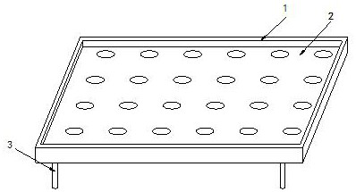
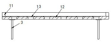
[0029] Its structure includes a main body 1, a water storage tank 2, and a fixed rod 3. The inner upper end of the main body 1 is provided with a water storage tank 2, and the fixed rods 3 are provided with four, and are respectively arranged at the bottom end of the main body 1. 1 includes a side plate 11, a support plate 12, and a through groove 13, the side plate 11 is arranged at the side end of the water storage tank 2, the support plate 12 is connected to the upper end of the fixed rod 3, and the through groove 13 is provided with eight above, and horizontally arranged on the upper end surface of the support plate 12 .

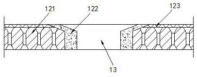
[0030] The support plate 12 includes a sand filtering device 121, an erecting device 122, and a sand filtering net 123. The sand filtering device 121 is arranged on the upper end of the fixed rod 3, and the erecting device 122 is in...

Embodiment 2

[0035] Example 2: Please refer to Figure 7-Figure 9 , the specific embodiments of the present invention are as follows:

[0036] The sand filter device 121 includes a sand filter body c1, a water channel c2, and a water inlet c3. The sand filter body c1 is arranged on the upper end of the fixed rod 3, and more than eight water channels c2 are arranged horizontally on the filter. The end face of the sand body c1, the water inlet c3 is located at the upper end of the water channel c2, and the width of the water inlet c3 gradually decreases from the upper end to the lower end, which is conducive to guiding the water to the water channel c2 through the water inlet c3.

[0037]The sand filter body c1 includes a flow channel c11, a sand control block c12, and a sand separation plate c13. The flow channel c11 is arranged inside the sand body c1, and there are more than eight sand control blocks c12, and each column There are two sand separation plates c13, which are respectively ar...


PUM


Abstract

The invention discloses a surface flow wetland purification device which structurally comprises a main body, a water storage tank and four fixing rods, wherein the water storage tank is arranged at the upper end of the interior of the main body, the four fixing rods are arranged at the bottom end of the main body, the main body comprises side plates, a supporting plate and a penetrating groove, the supporting plate comprises a sand filtering device, a vertical device and a sand filtering net, the vertical device comprises a vertical frame, a water flowing groove, a flow collecting groove and a supporting block, the supporting block comprises a supporting body, a deformation groove, a cutting groove and a contact block, and the contact block comprises a contact body, an empty groove and a friction block. Sand placed at the low end of the main body is pressed by using the sand filtering net, and moisture placed at the upper end of the main body can penetrate through the sand filtering net to flow downwards, so that soil can be compact and has sufficient moisture, roots and stems of plants can be pricked into sand, the situation that the plants topple over is avoided, and the survival rate of the plants is increased.

Description

technical field [0001] The invention relates to the field of artificial wetlands, in particular to a surface flow wetland purification device. Background technique [0002] The advantages of constructed wetlands are mainly reflected in low investment, low operation and management costs, use of renewable energy, strong adaptability to changes in water quantity and water quality, and ecological security. It makes full use of the physical, chemical and biological triple synergies of the substrate-microbe-plant complex ecosystem to purify sewage. [0003] Based on the above-mentioned inventor's discovery, the existing surface flow wetland purification device mainly has the following deficiencies, for example: when the sandy surface flow wetland is planting seeds in progress, due to the silt placed in the surface flow wetland Following the water loss, the geology of the surface wetland is relatively soft, which makes the plants with seeds on the surface wetland easy to dump, res...

Claims


Application Information

Patent Timeline
Patent Type & Authority Applications(China)
IPC IPC(8): A01G9/12A01G17/14C02F3/32
CPCA01G9/12A01G17/14C02F3/32
Inventor 陈开伟
Owner 西昌市巴汝国有林场
Why Eureka
Try Eureka