
Multifunctional integrated ultrasonic detection equipment

Inactive Publication Date: 2021-11-23
ZHEJIANG UNIV OF TECH
View PDF0 Cites 0 Cited by
  • Summary
  • Abstract
  • Description
  • Claims
  • Application Information

AI Technical Summary

Problems solved by technology

[0003] The purpose of the present invention is to solve the problems that the existing ultrasonic thickness measurement method and device have a lot of tools in use, which is very inconvenient, the spraying of the coupling agent is not uniform, and the grinding machine needs to be repositioned to waste time after grinding, and proposes a multifunctional integrated The advanced ultrasonic flaw tester enhances the efficiency of thickness measurement work, improves the way of grinding and the treatment of debris, and improves the way of couplant spraying

Method used


Image

  • Multifunctional integrated ultrasonic detection equipment
  • Multifunctional integrated ultrasonic detection equipment

Examples


Embodiment

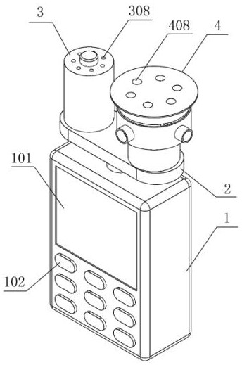
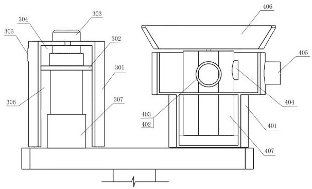
[0024] Multifunctional integrated ultrasonic testing equipment mainly includes ultrasonic thickness gauge host 1, bracket 2, ultrasonic probe device 3 and pneumatic grinding device 4.

[0025] The bracket 2 adopts a T-shaped structure and is arranged on the top of the main unit 1 of the ultrasonic thickness gauge, and the ultrasonic probe device 3 is arranged at one end of the bracket 2, and the coupling agent spraying and ultrasonic thickness measurement can be performed simultaneously through the ultrasonic probe device 3; the ultrasonic probe device 3 includes Probe housing 301, the interior of probe housing 301 is provided with a partition 302, thereby dividing probe housing 301 into an upper chamber 304 and a lower chamber 306, the upper chamber 304 is used to store couplant, and the upper end of the side is provided with an inlet The feed port 305 is used for couplant filling, and a plug is set at the feed port 305 to close the feed port 305; the top surface of the upper ...


PUM


Abstract

The invention discloses multifunctional integrated ultrasonic detection equipment, which comprises an ultrasonic thickness gauge host, an ultrasonic probe device and a pneumatic polishing device, wherein a bracket is arranged at the top part of the ultrasonic thickness gauge host, the ultrasonic probe device is arranged at one end of the bracket, and couplant spraying and ultrasonic thickness measurement can be carried out at the same time by means of the ultrasonic probe device; and the pneumatic grinding device is arranged at the other end of the bracket, and grinding and dust collection can be conducted at the same time through using the pneumatic grinding device. The multifunctional integrated ultrasonic detection equipment has the beneficial effects that the ultrasonic thickness gauge product integrating a grinding machine, a coupling agent tank and a thickness gauge can realize rapid positioning, grinding, coupling agent spraying and continuous measurement, and is convenient to operate; and the equipment is miniaturized, integrated and convenient to carry.

Description

technical field [0001] The invention relates to the technical field of ultrasonic detection, in particular to a multifunctional integrated ultrasonic detection device. Background technique [0002] Fatigue, creep, radiation and other damages that will occur when pressure-bearing equipment is in service, because they often involve high temperature, high pressure, corrosion, radiation and other environments, then become a threat to the service safety of special pressure-bearing equipment, leading to explosions and other sudden accidents main factor. With the continuous development of pressure equipment in extreme environments and extreme scales, it will inevitably bring about changes in failure modes and testing equipment. In order to ensure safety, it is necessary to develop corresponding detection equipment in order to quickly obtain corresponding evaluation data. At present, the ultrasonic thickness measurement methods and devices at home and abroad have the following pro...

Claims


Application Information

Patent Timeline
Patent Type & Authority Applications(China)
IPC IPC(8): G01B17/02
CPCG01B17/02
Inventor 郑水华李九龙刘建飞林伟徐逸伦
Owner ZHEJIANG UNIV OF TECH
Learn More