
Optical path folding reflection type large-view-field compound eye imaging optical system and method

An imaging optical and reflective technology, which is applied in optics, optical components, optical device exploration, etc., can solve the problems of high cost of spare parts, large volume and quality, and high image data generation, and achieves enlarged field of view, small size, and high application flexible effects

Pending Publication Date: 2021-11-23
SHENYANG LIGONG UNIV
View PDF9 Cites 0 Cited by
  • Summary
  • Abstract
  • Description
  • Claims
  • Application Information

AI Technical Summary

Problems solved by technology

[0005] Aiming at the problems existing in the prior art of the multi-camera array compound eye system with large volume and mass, high cost of spare parts, and excessive image data generation, the present invention provides an optical path folded reflective large field of view compound eye imaging optical system and its method. Design a multi-channel-single-detector bionic compound eye imaging system with a large field of view. By means of optical path refraction and optical path normalization, the multi-view sub-eye image plane coplanar and single photodetector partition imaging can be realized, which meets the lightweight design of the system. At the same time, the detection field of view is expanded, so that the compound eye system can achieve the advantages of low cost, small size, light weight, and wide detection field. Field of view visual imaging and detection support, can also be used independently to complete machine vision detection tasks such as large field of view monitoring, identification, and early warning

Method used


Image

  • Optical path folding reflection type large-view-field compound eye imaging optical system and method
  • Optical path folding reflection type large-view-field compound eye imaging optical system and method
  • Optical path folding reflection type large-view-field compound eye imaging optical system and method

Examples


Embodiment 1

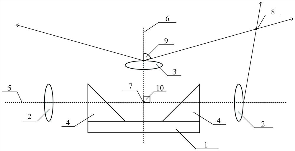
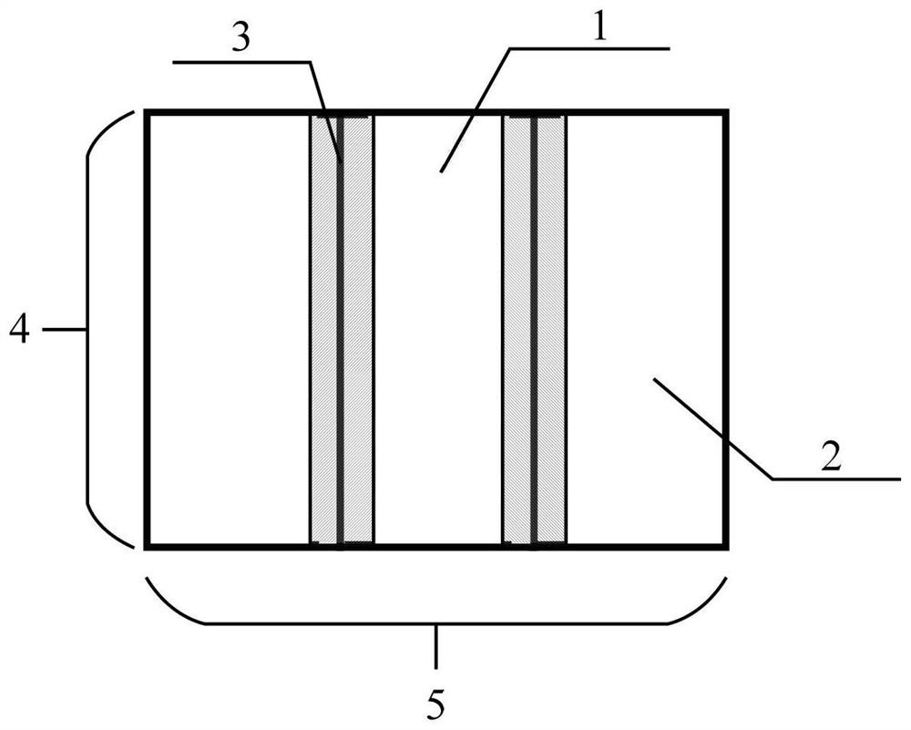
[0056] An optical path folded reflective large field of view compound eye imaging optical system, the system is an N-level imaging structure, N≥1, and each level of imaging structure consists of three sub-eye channels whose main optical axes are perpendicular to each other and located on the same plane under adjacent channels, and a The photodetector is composed of a photodetector target surface 1, an edge sub-glass group 2, a center sub-glass group 3 and a reversing prism 4; Figure 13 shown;

[0057] Two symmetrical reversing prisms 4 are arranged on both sides of the photodetector target surface 1, and a central sub-glasses group 3 is arranged in the middle Y-axis direction of the photodetector target surface 1, and the electric detector target surface 1 Two symmetrical edge sub-spectacles groups 2 are arranged in the direction of the X-axis at both ends of the outer side, and the mirror surfaces of the two edge sub-spectacles groups 2 face the right-angled surfaces of the t...


PUM


Abstract

An optical path folding reflection type large-view-field compound eye imaging optical system and method belong to the technical field of large-view-field optical imaging systems and bionic compound eye imaging detectors. The system is of an N-level imaging structure. Each level of imaging structure is composed of three sub-eye channels and a photoelectric detector, wherein the main optical axes of the adjacent channels are perpendicular to each other and located on the same plane. According to the system, a multi-channel-single-detector large-view-field bionic compound eye imaging system is designed; multi-view-angle sub-eye image plane coplane and single-photoelectric-detector partition imaging are achieved in an optical path refraction and reflection and optical path normalization mode; and the detection view field is enlarged while the system is light. The compound eye system has the advantages of being low in cost, small in size, light in weight, wide in detection area and the like, can be carried on load-limited platforms such as small unmanned equipment and low-speed projectiles, provides large-view-field visual imaging and detection support for the platforms, and can also be independently used to complete machine visual detection tasks such as large-view-field monitoring, recognition and early warning.

Description

technical field [0001] The invention belongs to the technical field of a large field of view optical imaging system and a bionic compound eye imaging detector, and in particular relates to a compact optical path folding reflection type large field of view compound eye imaging optical system and an imaging method thereof. Background technique [0002] At this stage, conventional visual imaging and detection devices adopt a single-mirror group-single photodetector configuration, that is, a traditional single-aperture imaging camera group. Constrained by the principle of optical imaging and the mapping relationship, the field of view of a single-aperture detector is inversely proportional to the focal length. As a result, this type of imaging system must sacrifice the detection distance and further expand the system aperture in order to achieve a large field of view detection capability. But if you want to further realize the miniaturization of the system under the premise of e...

Claims


Application Information

Patent Timeline
IPC IPC(8): G02B27/00G02B17/08G01V8/10
CPCG02B27/0081G02B27/0012G02B17/08G01V8/10
Inventor 郝永平曹昭睿
Owner SHENYANG LIGONG UNIV
Features
  • Generate Ideas
  • Intellectual Property
  • Life Sciences
  • Materials
  • Tech Scout
  • Unparalleled Data Quality
  • Higher Quality Content
  • 60% Fewer Hallucinations
Learn More