Array patch type radio fuse

A radio and patch technology, applied in electric fuzes, fuzes, weapon accessories, etc., can solve the problems of inability to switch directions in the digital domain, inability to obtain angle information, and good effect of multi-antenna fuzes, achieving small size and good detection effect. Effect

Pending Publication Date: 2021-11-26
SHANXI YUXIANG INFORMATION TECH CO LTD
6 Cites 0 Cited by

AI-Extracted Technical Summary

Problems solved by technology

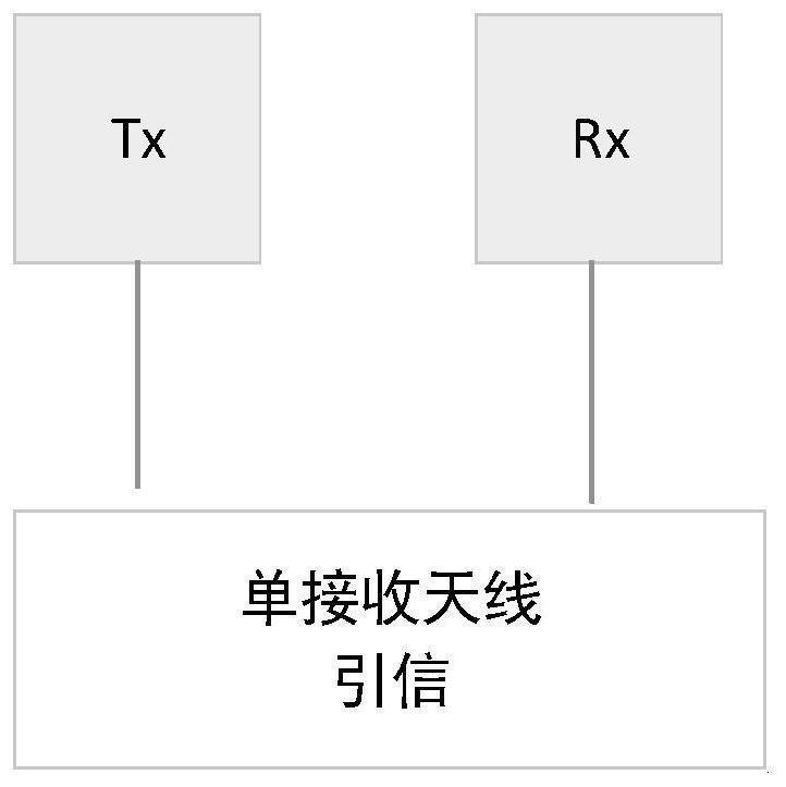
The single-antenna fuze has only one receiving channel, which can calculate the speed and distance information, but cannot obtain the angle information of the target. The single antenna cannot be be...

Abstract

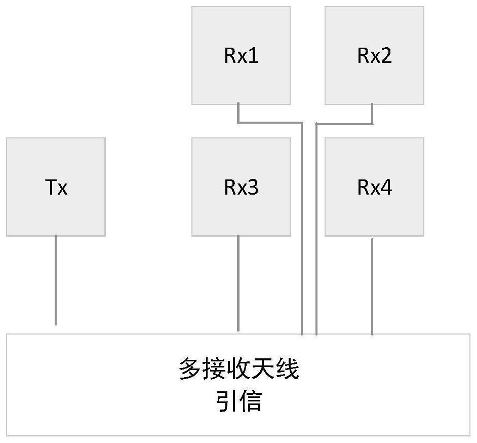
The invention discloses a radio fuse of an array patch antenna. The radio fuse comprises the array patch antenna, a multi-channel frequency modulation continuous wave transceiving circuit and a signal processing circuit. The array antenna can achieve beam forming, target detection is more flexible than a single antenna mode, the multi-antenna structure supports phase-comparison angle measurement, and angle information except distance and speed can be obtained. According to the array patch type radio fuse provided by the invention, a better fuze detection effect can be realized in a volume allowable range.

Application Domain

Electric fuzes

Technology Topic

TelecommunicationsSignal processing circuits +5

Image

  • Array patch type radio fuse
  • Array patch type radio fuse
  • Array patch type radio fuse

Examples

  • Experimental program(1)

Example Embodiment

[0020] DETAILED DESCRIPTION OF THE PREFERRED EMBODIMENTS
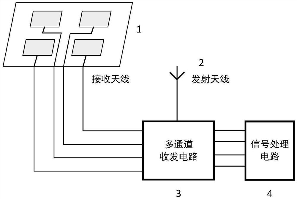
[0021] like figure 2 with image 3 As shown, an array-type radio trunk of the present invention includes an array patch receiving antenna 1, a patch emission antenna 2, a multi-channel transceiver circuit 3, and a signal processing circuit 4.
[0022] The plurality of separate patch antennas in the antenna 1 constitute an array to form a multi-channel array receiving antenna, and each receiving channel in the receiving circuit corresponds to a group element in the antenna in the antenna.
[0023] The transmitting antenna 2 also uses a patch antenna, an antenna may be in a single or array, the antenna polarization direction is the same as the receiving antenna, and the beam width can be customized as needed.
[0024] like Figure 4 As shown, the signal processing circuit built into a digital beamforming algorithm. Digital beamforming is directed to the array antenna, using the aperture of the array antenna, forming a received beam in a desired direction via a digital signal processing. Although the direction of the single antenna is whole, the signal of the plurality of receiving channels of the array, using the digital processing method, the incident signal in a certain direction, the compensation due to the propagation wave factor caused by the sensor in the spatial position The phase difference is achieved, thereby achieving the maximum energy receiving in this direction, completing the beam formation in this direction to receive a useful desired signal, which aggregate the direction gain received by the array in a designated direction, which is equivalent to formation A "beam". You can point to different directions by changing the weight, and the scanning of beam is achieved. Multiple beams can also be formed simultaneously by multi-channel parallel processing, and a suitable window function can also be selected to reduce the sub-valve level.
[0025] like Figure 5 As shown, the signal processing circuit built-in ratio phase measurement angle algorithm. The phase method angular angle utilizes the phase difference between the echo signals between the plurality of antennas. The signal reflected from the θ direction remote zone target, which can be approximately planar waves when reaching the receiving antenna. Since the two receiving antenna spacing is D, the received signal is existentant and the phase difference They meet between: Therefore, the phase calculation is used to compare the echo signal, and the phase difference is measured. You can determine the target direction θ, the calculation of the azimuth can be used
[0026] The above is only preferred embodiments of the invention, and is not intended to limit the invention, any modification, equivalent replacement, improvement, etc. according to the principle of the present invention, should be included within the scope of the invention.

PUM

no PUM

Description & Claims & Application Information

We can also present the details of the Description, Claims and Application information to help users get a comprehensive understanding of the technical details of the patent, such as background art, summary of invention, brief description of drawings, description of embodiments, and other original content. On the other hand, users can also determine the specific scope of protection of the technology through the list of claims; as well as understand the changes in the life cycle of the technology with the presentation of the patent timeline. Login to view more.

Similar technology patents

Image forming device

InactiveUS20060023319A1easily manufacturesmall size
Owner:KONICA MINOLTA PHOTO IMAGING

Seedling-growing tape and method of manufacturing the same

InactiveUS6460473B1small sizefacilitate handling
Owner:HONDA MOTOR CO LTD +1

Remote control lighting assembly and use thereof

ActiveUS20080211369A1small size
Owner:HONG KONG APPLIED SCI & TECH RES INST

Classification and recommendation of technical efficacy words

  • small size
  • Good detection effect

Microfabricated elastomeric valve and pump systems

InactiveUS6929030B2high speedsmall size
Owner:CALIFORNIA INST OF TECH

RFID antenna

InactiveUS20060208900A1high efficiencysmall size
Owner:TRANSPACIFIC TECH

Capacitor module, power converter, vehicle-mounted electrical-mechanical system

ActiveUS20070109715A1reduce surge voltagesmall size
Owner:HITACHI ASTEMO LTD

Projection display chip

InactiveUS20100321640A1small sizehigh efficiency
Owner:IND TECH RES INST

Phase-change energy-storage material nanocapsule and preparation method thereof

ActiveCN104449590Asmall sizeImprove stability
Owner:INST OF CHEM MATERIAL CHINA ACADEMY OF ENG PHYSICS

Identity authentication system based on living body detection and face verification

InactiveCN107133608AHigh-precision face recognition and liveness detectionGood detection effect
Owner:天津中科智能识别有限公司

Passive positioning and identification system for civil unmanned aerial vehicles

ActiveCN107678023AGood ability to detect low-altitude, slow-moving and small targetsGood detection effect
Owner:芜湖华创光电科技有限公司

X-ray crystal orientation device

Owner:DONGDAN AOLONG RADIATIVE INSTR GRP

Ablation catheter having pressure detecting function

ActiveCN106974724AElastic fitGood detection effect
Owner:四川锦江电子医疗器械科技股份有限公司
Why Eureka
Try Eureka