Automatic monitoring system terminal for hydrological information of inland river
A hydrological information and monitoring system technology, applied in open-air water source surveying, measuring devices, surveying and navigation, etc., can solve problems such as affecting river analysis results, affecting real-time detection, and incomplete on-site, so as to facilitate hydrological monitoring and facilitate monitoring of water levels. , the effect of maintaining stability
- Summary
- Abstract
- Description
- Claims
- Application Information
AI Technical Summary
Problems solved by technology
Method used
Image


Examples
Embodiment 1
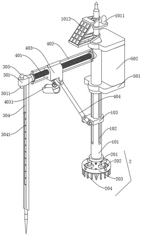
[0037] The present invention proposes a hydrological information automation monitoring system terminal of a inner river, including the mounting portion 1; the bottom of the mounting portion 1 is provided with a stable portion 2, and the fixed sleeve 201 of the stabilizing portion 2 is fixed to the bottom of the vertical rod 101 by screws. The monitoring portion 3, the monitoring portion 3 is disposed at the intermediate position of the left side of the mounting portion 1, and the monitoring portion 3 stabilizer 302 is fixed to the mounting groove 104; the control portion 4, the control portion 4 is rotated to the mounting groove In 104, and the drive motor in the control rod 401 and the mounting groove 104 is connected by a tapered teeth, and the lever 401 rotates on the stabilizing rod 302, and the connecting frame 404 of the control portion 4 rotates on the sliding block 103; data part 5, the mounting plate 501 of the data portion 5 is fixed to the vertical rod 101 by the screw, a...
Embodiment 2
[0041] like figure 1 As shown, the stabilizing portion 2 includes a fixed sleeve 201, a fixed sleeve 201 is a circular structure, and a circular projection is provided at the top of the fixed sleeve 201; the fixed sleeve 201 is used to mount the stabilizing portion 2; the fixing frame 202 The fixing frame 202 is a rectangular structure, and the mount 202 is fixedly attached to the outer wall of the fixed sleeve 201; the fixing frame 202 is used to stabilize the mounting ring 203; the mounting ring 203, the mounting ring 203 is a circular structure, and the mounting ring 203 is fixed Connecting on the fixing frame 202; mounting ring 203 for mounting a ring ring 204; a ring ring 204, a ring ring 204 is a circular structure, and a rectangular card teeth are provided at the bottom of the tooth ring 204, and the tooth ring 204 is fixed to the mounting The bottom of the ring 203; the teeth 204 are used in the fixing device, and the dirt loss is reduced by snipping.
[0042] By the teeth...
Embodiment 3
[0044] like Image 6 As shown, the monitoring portion 3 includes: mounting block 301, mounting block 301 is a rectangular block structure, and a circular groove is provided on the right side of the mounting block 301; mounting block 301 is used to mount other structures of the monitoring portion 3; water level monitoring The model 3011, the model of the water level monitor 3011 is an HCDAR-8H frequency modulation continuous wave radar, and the water level monitor 3011 is disposed at the bottom of the mounting block 301; the water level monitor 3011 is used to monitor the water level of the river; stabilizing rod 302, stabilizer 302 is a cylindrical rod-shaped structure, and the stabilizer rod 302 is fixed within the circular groove of the mounting block 301; the stabilizer 302 is used to support the control portion 4; the warning 303, the warning 303 is a cylindrical structure, and the warning 303 is installed On the stabilizer rod 302, the model of the warning 303 is a M4-50S thre...
PUM
 Abstract
Description
Claims
Application Information
 - R&D
- Intellectual Property
- Life Sciences
- Materials
- Tech Scout
- Unparalleled Data Quality
- Higher Quality Content
- 60% Fewer Hallucinations
Browse by: Latest US Patents, China's latest patents, Technical Efficacy Thesaurus, Application Domain, Technology Topic, Popular Technical Reports.
© 2025 PatSnap. All rights reserved.Legal|Privacy policy|Modern Slavery Act Transparency Statement|Sitemap|About US| Contact US: help@patsnap.com