
Optical fiber state detection method from local side to remote side

A status detection and remote technology, applied in the field of communication network, can solve the problems that resource allocation and working status cannot be grasped in real time, there is no monitoring and management of dumb resource link status, and dumb resources have no effective supervision, etc., so as to facilitate deployment and maintenance effects

Pending Publication Date: 2021-11-26
中国联合网络通信有限公司广东省分公司
View PDF3 Cites 0 Cited by
  • Summary
  • Abstract
  • Description
  • Claims
  • Application Information

AI Technical Summary

Problems solved by technology

At present, most of the dumb resources in optical communication boxes are not effectively supervised, and the allocation and work status of resources cannot be grasped in real time
[0003] The current resource supervision adopts the manual inspection mode to ensure the normal operation of the box. This mode has high operating costs and poor actual results
[0004] From the perspective of intelligent technology, most of the current research progress is to monitor the location information, temperature and humidity, vibration displacement, etc. of the optical box through the Internet of Things technologies such as intelligent electronic locks and intelligent gateways. In terms of environmental information and other aspects, there is no solution for monitoring and managing the link status in dumb resources

Method used


Image

  • Optical fiber state detection method from local side to remote side
  • Optical fiber state detection method from local side to remote side
  • Optical fiber state detection method from local side to remote side

Examples


Embodiment Construction

[0042] In order to make the objects, technical solutions and advantages of the present invention, the present invention will be described in detail below, but the scope of the present invention is not limited to the following specific embodiments.

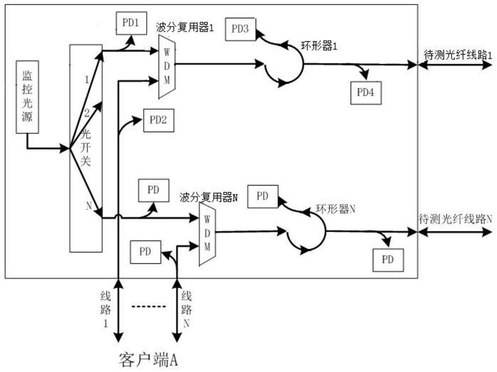
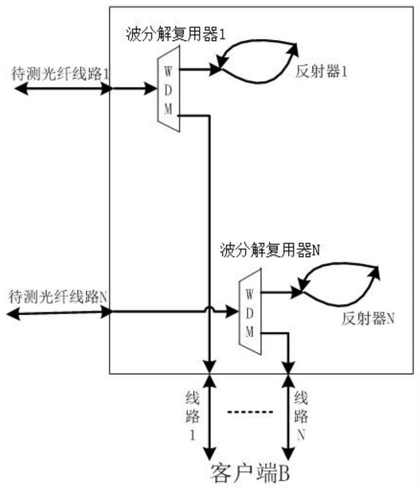
[0043] like Figure 1-3 As shown, an optical fiber state detection method of a local end to the distal end includes the following steps:

[0044] Step 1: The monitoring light source of the local client issues a detection optical signal, the detecting optical signal outputs within the active device, and is input to the N road unit detection optical path in the optical switch of the active device, and enter the unit. After the detection of the optical path, enter the wavelength division multiplexer;

[0045] Step 2: After the local client issues a data service optical signal into the excessive wavelength division, 1% light enters the second photodetector of the active device to detect the online state of the probe data P2 to determine the...


PUM


Abstract

The invention discloses an optical fiber state detection method from a local side to a remote side, which comprises the following steps: a monitoring light source of a local side client sends a detection light signal, and the detection light signal is output into active equipment; after a data service optical signal sent by a local client is subjected to wave separation by a wave separator, 1% of light enters a second optical detector to be detected to obtain P2, and the online state of the service is judged; the rest 99% of the optical signals are input into the wavelength division multiplexer of the active equipment, are combined with the optical signals output by the optical switch, and then are transmitted to a far-end client through a to-be-tested optical fiber line; and a detection optical signal and a data service optical signal are separated from passive equipment of a far-end client through a wavelength division demultiplexer, the detection optical signal is reflected back to the wavelength division demultiplexer in a reflector, and the data service optical signal is output to a client receiving end after passing through the reflector. According to the invention, each core is independently monitored, each path of light source is independent and can be used without configuration, and the availability of each path of fiber core and online monitoring of service can be obtained.

Description

Technical field [0001] The present invention relates to the field of communication networks, and more particularly to an optical fiber state detection method of a local end to the distal end. Background technique [0002] In the carrier's network, there is a large number of passive networks, which cannot be automatically reported to their own information, called "dumb resources". At present, most of the optical boxes have no effective supervision, the distribution of resources and the work conditions cannot be mastered in real time. [0003] The current resource supervision adopts human inspection mode to ensure the normal operation of the box, which is high in operation, and the actual effect is poor. [0004] Most of the current research progress from intelligent technical perspectives is a plan to monitor the location information, temperature and humidity, vibration displacement of optical boxes, etc., which is concentrated in preventing damage, unlock permission, etc. Environ...

Claims


Application Information

Patent Timeline
IPC IPC(8): H04B10/071H04J14/02
CPCH04B10/071H04J14/0227
Inventor 骆益民黄志新陈烈强赖柏辉徐远佃何小婵江永杰刘年王剑锋余冬玲杨文伟孙地
Owner 中国联合网络通信有限公司广东省分公司
Learn More