
Rust removal robot based on ultrahigh pressure water

An ultra-high pressure and robotic technology, applied in the field of robotics, can solve problems such as affecting the appearance, low efficiency of rust removal, and limited spray area of ​​the nozzle, so as to improve safety, efficiency, rust removal effect and gloss.

Inactive Publication Date: 2021-11-30
深圳中科智清机器人服务有限公司
View PDF0 Cites 1 Cited by
  • Summary
  • Abstract
  • Description
  • Claims
  • Application Information

AI Technical Summary

Problems solved by technology

[0004] The purpose of the present invention is to solve the rust removal robot existing in the prior art due to the limited spray area of ​​the nozzle, resulting in low efficiency of rust removal, and the impact of rust stains often left after rust removal by high-pressure water jetting Aesthetic shortcomings, and proposed a derusting robot based on ultra-high pressure water

Method used


Image

  • Rust removal robot based on ultrahigh pressure water
  • Rust removal robot based on ultrahigh pressure water
  • Rust removal robot based on ultrahigh pressure water

Examples


Embodiment 1

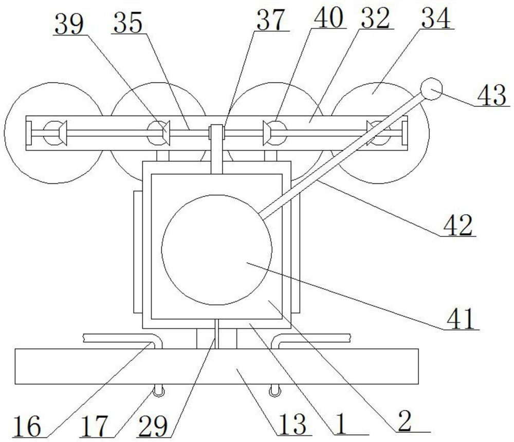
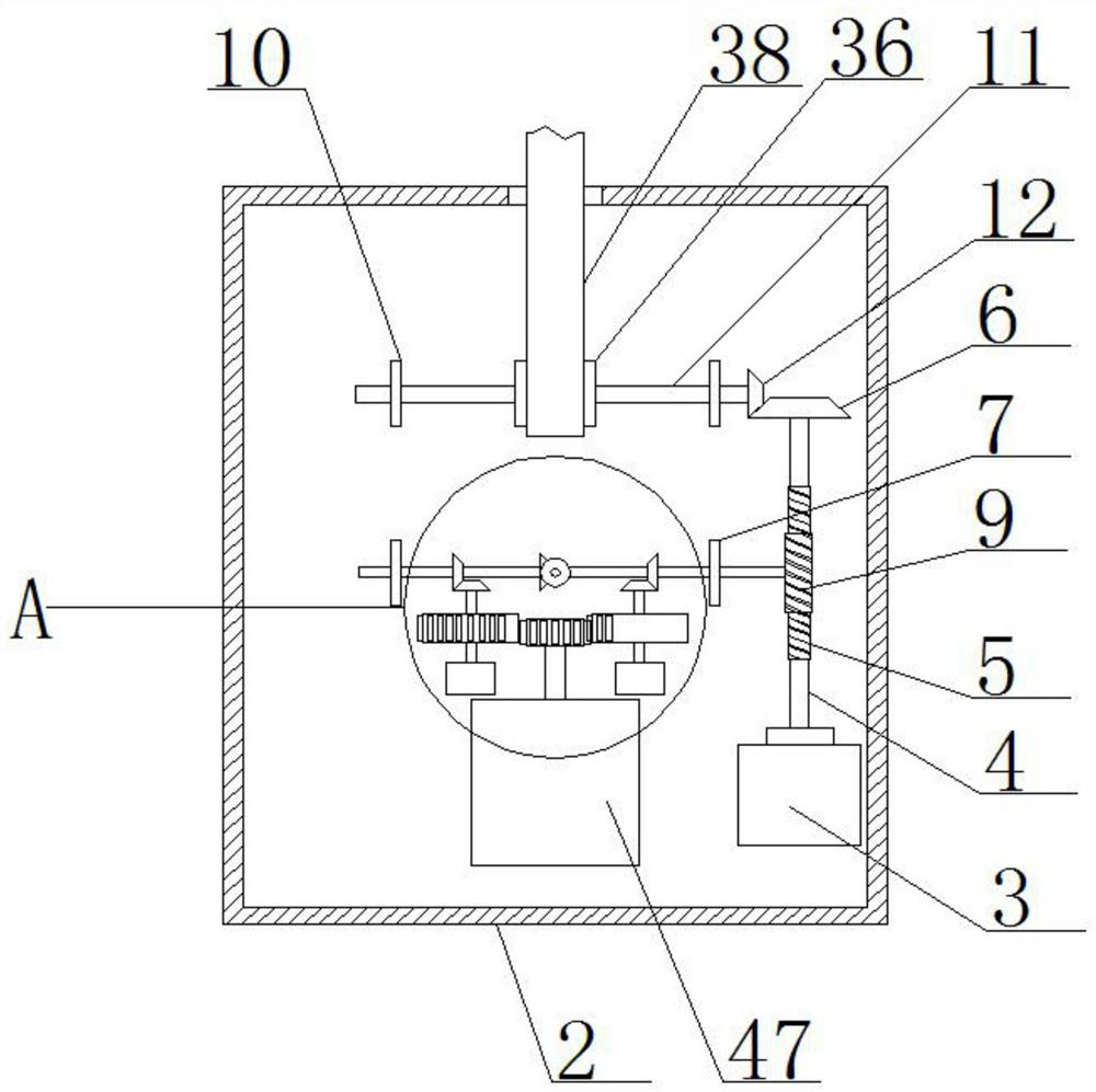
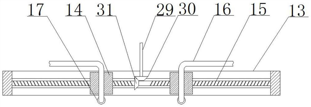
[0030] refer to Figure 1-6 , a rust removal robot based on ultra-high pressure water, comprising a mobile robot main body 1, the top of the mobile robot main body 1 is fixedly connected with a protective shell 2 by bolts, and a motor 3 is fixedly installed in the protective shell 2 by bolts, and the mobile robot main body The front end of 1 is provided with a high-pressure water derusting mechanism, the rear end of the main body of the mobile robot 1 is provided with a polishing mechanism, the top of the protective shell 1 is provided with an ultrasonic radar navigation mechanism, and the motor 3 is connected with the high-pressure water derusting mechanism, polishing mechanism and ultrasonic radar. In cooperation with the navigation mechanism, the output shaft of the motor 3 is welded with a first rotating shaft 4, the outer side of the first rotating shaft 4 is provided with a worm screw 5 through a welding fixed sleeve, and one end of the first rotating shaft 4 is fixedly c...

Embodiment 2

[0042] The difference from Embodiment 1 is that it includes a mobile robot main body 1, a protective housing 2 is fixedly connected to the top of the mobile robot main body 1, a motor 3 is fixedly installed in the protective housing 2, and a high-voltage The water derusting mechanism, the rear end of the main body 1 of the mobile robot is provided with a polishing mechanism, the top of the protective shell 1 is provided with an ultrasonic radar navigation mechanism, and the motor 3 cooperates with the high-pressure water derusting mechanism, the polishing mechanism and the ultrasonic radar navigation mechanism. The output shaft of 3 is welded with a first rotating shaft 4, the outer fixed sleeve of the first rotating shaft 4 is provided with a second small bevel gear, and one end of the first rotating shaft 4 is fixedly connected with a large bevel gear 6, and the protective shell 2 Two first bearings 7 are arranged inside, and the same first rotating rod 8 is arranged on the t...


PUM


Abstract

The invention belongs to the field of robots, and particularly relates to a rust removal robot based on ultrahigh pressure water. The following scheme is provided for solving the problems that according to an existing rust removal robot, due to the fact that the spraying area of a spraying head is limited, the rust removal efficiency is low, and after high pressure water spraying rust removal, spots generated by rusting are often left, and attractiveness is affected. The rust removal robot comprises a movable robot main body, a protection shell is fixedly connected to the top of the movable robot main body, a motor is fixedly arranged in the protection shell, and a high pressure water rust removal mechanism is arranged at the front end of the movable robot main body. During use, the spraying area of the high pressure water can be effectively increased, the rust removal efficiency is improved, the part obtained after high pressure rust removal can be synchronously polished and ground again, the rust removal effect and gloss of the metal surface are effectively improved, a surrounding ultrasonic radar probe is used for detection and navigation, and the use safety is higher.

Description

technical field [0001] The invention relates to the technical field of robots, in particular to a derusting robot based on ultra-high pressure water. Background technique [0002] High-pressure water jet derusting is an environmentally friendly and economical new surface treatment method. It uses the high-speed flow of water to remove the rust caused by metal surface corrosion. With the help of a mobile robot, it can automatically remove large areas of rust. Effectively relieves human labor; [0003] However, due to the limited spraying area of ​​the nozzle, the existing derusting robot has low derusting efficiency, and after derusting by high-pressure water jetting, the stains produced by rust often remain and affect the appearance. Contents of the invention [0004] The purpose of the present invention is to solve the rust removal robot existing in the prior art due to the limited spraying area of ​​the nozzle, resulting in low efficiency of rust removal, and the impact...

Claims


Application Information

Patent Timeline
IPC IPC(8): B24C1/08B24C3/06B24C9/00B24B27/033B24B27/00B25J11/00B25J19/02
CPCB24C1/086B24C3/06B24C9/00B24B27/033B24B27/0076B25J11/0065B25J19/026
Inventor 章斌
Owner 深圳中科智清机器人服务有限公司
Learn More