A lead frame feeding and conveying device

A technology of lead frame and conveying device, which is applied in the direction of conveyors, conveyor objects, transportation and packaging, etc., which can solve the problem of inability to ensure that the lead frame can be accurately moved to the next station, poor stability and accuracy of lead frame transportation, and inconvenience Problems such as installation and commissioning of the device, to prevent deviating from the track, improve adsorption stability, and prevent slipping

Active Publication Date: 2022-02-11
四川富美达微电子有限公司
View PDF8 Cites 0 Cited by
  • Summary
  • Abstract
  • Description
  • Claims
  • Application Information

AI Technical Summary

Problems solved by technology

Because the lead frame will slip due to the way of friction, it is impossible to ensure that the lead frame moves to the next position accurately, so it is necessary to add a position detection sensor to ensure that the lead frame is in place
However, the structure of this kind of device is relatively complicated, and there are many electrical control links, which is not only inconvenient for installation and debugging of the device, but also has a relatively high failure rate in later use.
Moreover, the transportation method using friction will lead to poor stability and accuracy of lead frame transportation.

Method used


Image

  • A lead frame feeding and conveying device
  • A lead frame feeding and conveying device
  • A lead frame feeding and conveying device

Examples


Embodiment

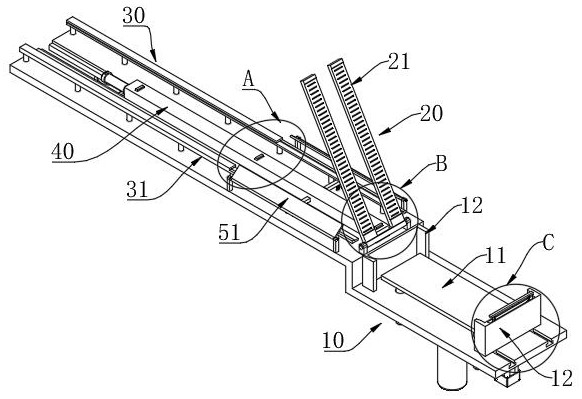
[0047] Such as figure 1 As shown, a lead frame feeding and conveying device includes: a storage mechanism 10 , a turning suction cup 20 and a conveying mechanism 30 arranged in sequence.

[0048] Specifically, the storage mechanism 10 is provided with a lifting plate 11, and the top surface of the lifting plate 11 is used for stacking and storing lead frames, and the pins of the lead frames face downward when stacked. The lifting plate 11 is moved vertically, and the lifting plate is driven by a linear servo motor, so that the lifting distance can be controlled more accurately.

[0049] Specifically, the rear end of the flip suction cup 20 is provided with a rotating shaft, the rotating shaft is located between the storage mechanism 10 and the conveying mechanism 30, the rotating shaft is perpendicular to the line between the storing mechanism 10 and the conveying mechanism 30, and is parallel to the lifting plate 11, Turn over suction cup 20 and turn its rotating shaft to rota...


PUM


Abstract

The present application provides a lead frame feeding and conveying device, including: a material storage mechanism, a turning suction cup, and a conveying mechanism. The stocking mechanism is provided with a lifting plate that moves vertically and is used for storing the lead frame. The flip suction cup is rotated and set; the front part of the flip suction cup is a pair of parallel and spaced suction plates, and there are multiple ventilation holes on one side of the suction plate. The conveying mechanism includes a pair of rails arranged at intervals, and the rails are in an L-shaped structure; the middle position of the rails is moved along the length direction and a push plate is provided, and the top surface of the push plate is provided with multiple paddles at intervals along the length direction, and the size of the interval is larger than that of the lead frame. Length; the paddle can be protruded or hidden in the push plate; there is a gap between the push plate and the rails on both sides. When the suction cup is turned over and turned to the conveying mechanism, the two suction plates are respectively located in the gap between the push plate and the rails on both sides. It has high adsorption firmness, which can prevent the lead frame from falling during the feeding process; at the same time, it can transport the lead frame more stably and accurately.

Description

technical field [0001] The invention belongs to the technical field of semiconductor device packaging, in particular to a lead frame feeding and conveying device. Background technique [0002] For semiconductor devices, chips are usually solidified on the leads of the lead frame, and then individual devices are formed through processes such as packaging and rib cutting. The leads of the lead frame usually have a bent structure, so that a part of the lead protrudes from the entire plane of the lead frame. In the production process, multiple processes require fast feeder delivery of the lead frame. When feeding, most of the existing equipment adopts a plurality of straws to absorb the lead frame through negative pressure; and usually when feeding the machine, the protruding side of the pin is set on the top to facilitate sticking the core; however In this case, there are relatively few positions on the lead frame for suction of the straw, and the overall area will not be too...

Claims


Application Information

Patent Timeline
Patent Type & Authority Patents(China)
IPC IPC(8): H01L21/677B65G47/91B65G19/02
Inventor 曾尚文刘高宸陈久元杨利明
Owner 四川富美达微电子有限公司
Why Eureka
Try Eureka