Power supply control system and method of multi-tab battery and electronic equipment

A multi-pole ear, charge and discharge control technology, applied in control/regulation systems, battery circuit devices, and conversion equipment without intermediate conversion to AC, etc., can solve the difficulties of battery terminal circuit board wiring and heat dissipation, battery terminal circuit Serious board heating, hardware cost increase and other problems, to achieve the effect of improving charging efficiency, reducing heat generation, and reducing charging time

Pending Publication Date: 2021-11-30
MEIZU TECH CO LTD
View PDF0 Cites 0 Cited by
  • Summary
  • Abstract
  • Description
  • Claims
  • Application Information

AI Technical Summary

Problems solved by technology

However, when the single-cell battery is fully charged, the voltage is about 4.5V. When the charging current exceeds 8A, the battery terminal circuit board will heat up very seriously.
For this, usually the battery connector also needs to be replaced with a battery connector with a lower impedance and a larger flow rate, resulting in increased hardware costs; at the same time, the wiring and heat dissipation treatment in the battery terminal circuit board will also be more difficult
In order to meet the heat dissipation requirements, the charging power of the battery terminal of the usual single cell is about 36W, resulting in low charging efficiency

Method used


Image

  • Power supply control system and method of multi-tab battery and electronic equipment
  • Power supply control system and method of multi-tab battery and electronic equipment
  • Power supply control system and method of multi-tab battery and electronic equipment

Examples


Embodiment Construction

[0064] In order to more clearly understand the above objects, features and advantages of the present disclosure, the solutions of the present disclosure will be further described below. It should be noted that, in the case of no conflict, the embodiments of the present disclosure and the features in the embodiments can be combined with each other.

[0065] In the following description, many specific details are set forth in order to fully understand the present disclosure, but the present disclosure can also be implemented in other ways than described here; obviously, the embodiments in the description are only some of the embodiments of the present disclosure, and Not all examples.

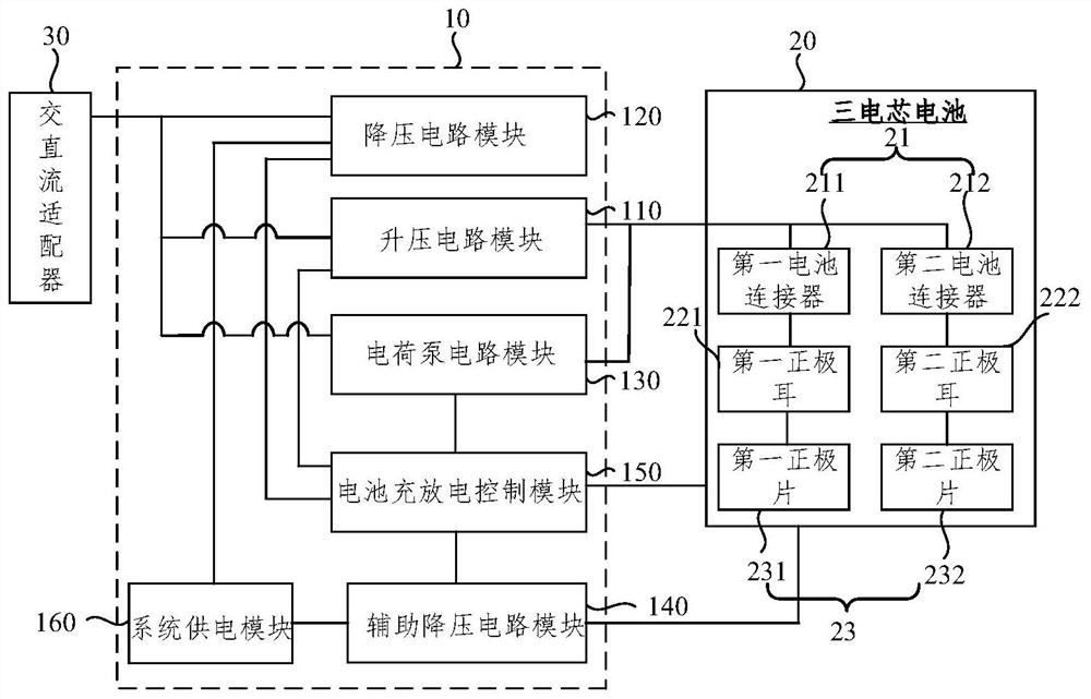
[0066] figure 1 It is a schematic structural diagram of a power control system for a multi-tab battery provided by an embodiment of the present disclosure, as shown in figure 1 As shown, it includes a charging and discharging circuit 10 and a three-cell battery 20, the three-cell battery 20 inc...


PUM


Abstract

The invention relates to a power supply control system and method of a multi-tab battery and electronic equipment. The power supply control system comprises a charging and discharging circuit and a three-cell battery, wherein the three-cell battery comprises battery connectors, and the battery connectors at least comprise a first battery connector and a second battery connector; the charging and discharging circuit comprises a step-up circuit module, a step-down circuit module, a charge pump circuit module, an auxiliary step-down circuit module, a battery charging and discharging control module and a system power supply module; the battery charging and discharging control module is a control module for controlling the step-up circuit module, the step-down circuit module, the charge pump circuit module and the auxiliary step-down circuit module to work in corresponding charging and discharging stages; the step-up circuit module works in a trickle charging stage, a constant-voltage charging stage and a charging cut-off stage; the charge pump circuit module works in a constant-current charging stage; the step-down circuit module works in a constant-current charging stage, a constant-voltage charging stage and a charging cut-off stage; and the auxiliary step-down circuit module works in a discharging stage, so that the charging efficiency is improved.

Description

technical field [0001] The present disclosure relates to the technical field of battery charging, and in particular to a power control system, a control method and electronic equipment of a multi-pole battery. Background technique [0002] A rechargeable battery is a rechargeable battery with a limited number of charging times and can be used with a charger. By charging the battery, the battery can be reused, which is beneficial to meet the needs of economy and environmental protection. The charging process of a battery is the reverse process of its discharging process, specifically, the process of converting electrical energy into chemical energy stored in the battery. [0003] In current electronic devices, single-cell batteries are mainly used for charging. However, when the single-cell battery is fully charged, the voltage is about 4.5V. When the charging current exceeds 8A, the battery terminal circuit board will heat up very seriously. For this, usually the battery ...

Claims


Application Information

Patent Timeline
Patent Type & Authority Applications(China)
IPC IPC(8): H02J7/00H02J7/02H02J7/10H02M3/07H02M3/156
CPCH02J7/0029H02J7/0068H02J7/00712H02J7/00714H02J7/00716H02J7/007182H02J7/02H02J7/06H02M3/07H02M3/156Y02B40/00
Inventor 陈佳
Owner MEIZU TECH CO LTD
Why Eureka
Try Eureka