Efficient industrial denitration device

A denitrification and industrial technology, applied in the field of high-efficiency industrial denitrification devices, can solve the problems of low denitrification efficiency, reduced work efficiency and performance, and inability to perform rapid denitrification, so as to improve denitrification efficiency, improve denitrification efficiency and performance, and effectively Conducive to the effect of environmental protection

Pending Publication Date: 2021-12-03
刘栋
View PDF6 Cites 0 Cited by
  • Summary
  • Abstract
  • Description
  • Claims
  • Application Information

AI Technical Summary

Problems solved by technology

[0005] Aiming at the deficiencies of the prior art, the present invention provides an efficient industrial denitrification device, which solves the problem that a large amount of retention is likely to occur when the traditional industrial denitrification device is performing denitrification work, and secondary or multiple denitrification is required, so that the overall denitrification Low efficiency, unable to perform rapid denitrification, reducing work efficiency and performance problems

Method used


Image

  • Efficient industrial denitration device
  • Efficient industrial denitration device
  • Efficient industrial denitration device

Examples


Embodiment example 1

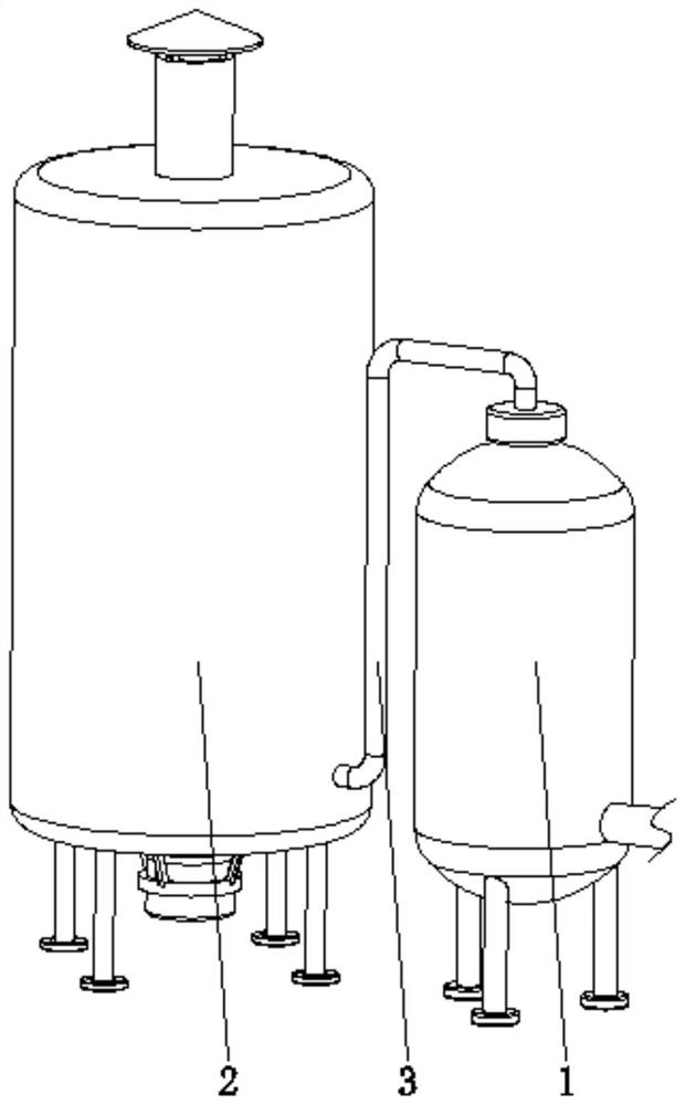
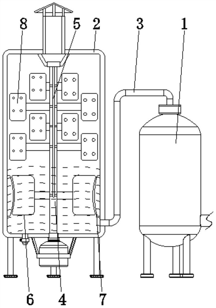
[0031] see Figure 1-7 , the present invention provides a technical solution: a high-efficiency industrial denitrification device, including a catalytic tank 1, a denitrification tank 2, and a connecting pipe 3, and the catalytic tank 1 and the denitration tank 2 are connected through the connecting pipe 3;

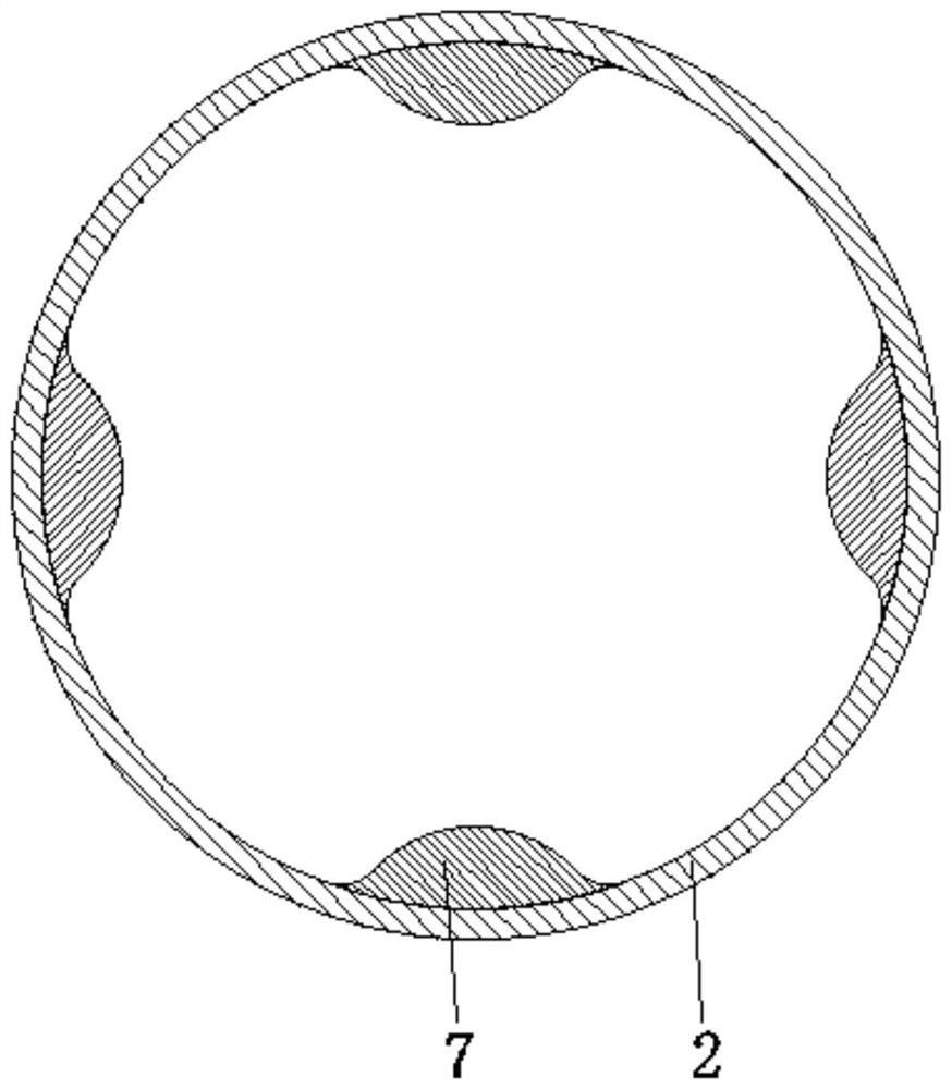
[0032] The interior of the denitrification tank 2 is provided with a driving shaft 4, a channel 5, a liquid mixing device 6, an arc surface bump 7, and a spraying device 8, and the driving shaft 5 is rotatably connected between the top and the bottom of the inner wall of the denitrification tank 2. , the channel 5 is opened at the central position inside the driving shaft 4, the liquid mixing device 6 is arranged at the bottom of the surface of the driving shaft 4, the arc-shaped protrusion 7 is fixed inside the denitrification tank 2 and corresponds to the position of the liquid mixing device 6, and the spraying device 8 is arranged on the top of the surface of the drivi...

Embodiment example 2

[0034] The liquid mixing device 6 is provided with a support rod 61, a liquid flow channel 62, and a stirring device 63. One end of the support rod 61 is fixedly connected to the surface of the drive shaft 4, and the liquid flow channel 62 is set at the inner center of the support rod 61 and connected to the channel 5. connected, the stirring device 63 is arranged on the end of the support rod 61 away from the driving shaft 4, when the gas in the connecting pipe 3 enters the denitrification tank 2, the gas reacts with the alkaline solution in the denitrification tank 2, and is driven by the driving shaft 4 Next, at this time, the support rod 61 and the stirring device 63 rotate at the same time, and then the alkaline solution is stirred, so that the gas is fully reacted, which is conducive to rapid denitrification and improves the denitrification efficiency.

[0035] The stirring device 63 is provided with an arc plate 631, a U-shaped sleeve 632, an elastic capsule body 633, an...

Embodiment example 3

[0037]The spraying device 8 is provided with a connecting rod 81, a spray flow channel 82, and a fan plate device 83. One end of the connecting rod 81 is fixedly connected with the surface top of the drive shaft 4, and the spray flow channel 82 is set at the inner central position of the connecting rod 81 and is connected to the channel. 5 connected, the fan device 83 is fixed on the end of the connecting rod 81 away from the driving shaft 4, when the driving shaft 4 rotates, it will drive the connecting rod 81 and the fan device 83 to rotate at the same time, and the inclined fan device 83 is rotating Under certain circumstances, the sprayed alkaline mist is fully stirred and mixed with the remaining toxic and harmful gases to reduce the emission of residual toxic and harmful gases, which is conducive to further denitrification.

[0038] The fan plate device 83 is provided with a plate body 831, an airflow hole 832, and a spray head 833. The plate body 831 is fixedly connected...


PUM


Abstract

The invention discloses an efficient industrial denitration device which comprises a catalysis tank, a denitration tank and a connecting pipe, the catalysis tank is communicated with the denitration tank through the connecting pipe, and a driving rotating shaft, a channel, a liquid mixing device, a cambered surface protruding block and a spraying device are arranged in the denitration tank. The driving rotating shaft is rotationally connected between the two corresponding sides of the top and the bottom of the inner wall of the denitration tank, the channel is formed in the center of the interior of the driving rotating shaft, the liquid mixing device is arranged at the bottom of the surface of the driving rotating shaft, the cambered surface protruding block is fixed to the position, corresponding to the liquid mixing device, in the denitration tank, and the spraying device is arranged at the top of the surface of the driving rotating shaft. According to the efficient industrial denitration device, the purpose of efficient denitration is achieved, flue gas can be rapidly denitrated, residues are reduced, emission of harmful gas is reduced, environmental protection is facilitated, repeated denitration is not needed, and the denitration efficiency and the use performance are improved.

Description

technical field [0001] The invention relates to the technical field of industrial denitrification, in particular to an efficient industrial denitrification device. Background technique [0002] Flue gas desulfurization and denitrification technology is a boiler flue gas purification technology applied to the chemical industry where nitrogen oxides and sulfur oxides are generated. Nitrogen oxides and sulfur oxides are one of the main sources of air pollution. Ambient air purification has many benefits. Currently known flue gas desulfurization and denitrification technologies include PAFP, ACFP, pyrolusite method, electron beam ammonia method, pulse corona method, gypsum wet method, catalytic oxidation method, microbial degradation method and other technologies. Most of the simultaneous gas desulfurization and denitrification technologies are currently in the research and industrial demonstration stages, but because they can simultaneously achieve desulfurization and denitrifi...

Claims


Application Information

Patent Timeline
Patent Type & Authority Applications(China)
IPC IPC(8): B01D53/86B01D53/78B01D53/56
CPCB01D53/56B01D53/78B01D53/8631
Inventor 刘栋
Owner 刘栋
Why Eureka
Try Eureka