Battery energy processing device and method and vehicle

A battery energy and processing device technology, applied in the field of vehicle control, can solve problems such as prominent electromagnetic compatibility problems, electromagnetic interference, and complex circuit topology of new energy vehicles, and achieve the effect of improving electromagnetic compatibility performance and reducing ripple current

Pending Publication Date: 2021-12-03
BYD CO LTD
View PDF0 Cites 1 Cited by
  • Summary
  • Abstract
  • Description
  • Claims
  • Application Information

AI Technical Summary

Problems solved by technology

[0003] Vehicle-mounted high-power electronic devices often generate serious electromagnetic interference, leading to increasingly prominent electromagnetic compatibility prob

Method used


Image

  • Battery energy processing device and method and vehicle
  • Battery energy processing device and method and vehicle
  • Battery energy processing device and method and vehicle

Examples


Embodiment Construction

[0072] Specific embodiments of the present disclosure will be described in detail below in conjunction with the accompanying drawings. It should be understood that the specific embodiments described here are only used to illustrate and explain the present disclosure, and are not intended to limit the present disclosure.

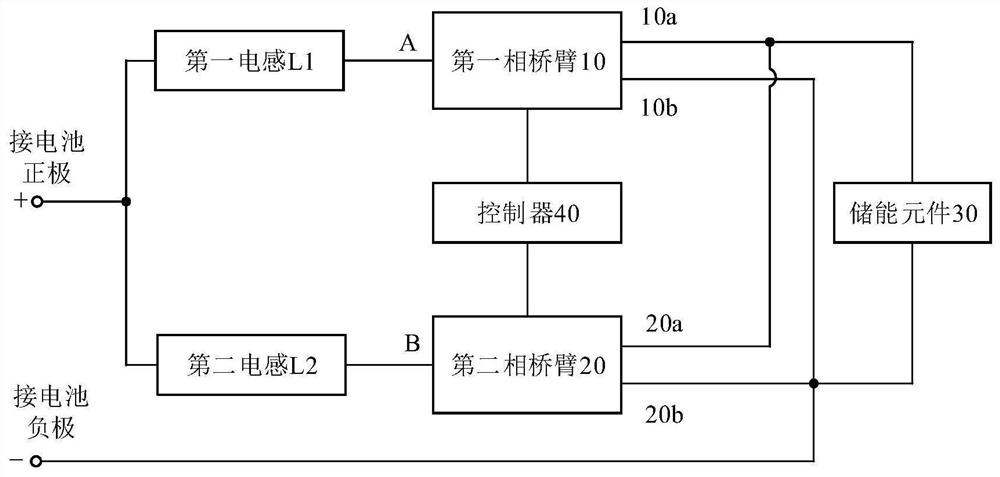
[0073] figure 1 It is a structural block diagram of a battery energy processing device provided by an exemplary embodiment. The battery energy processing device may include a first inductor L1 , a second inductor L2 , a first phase bridge arm 10 , a second phase bridge arm 20 , an energy storage element 30 and a controller 40 .

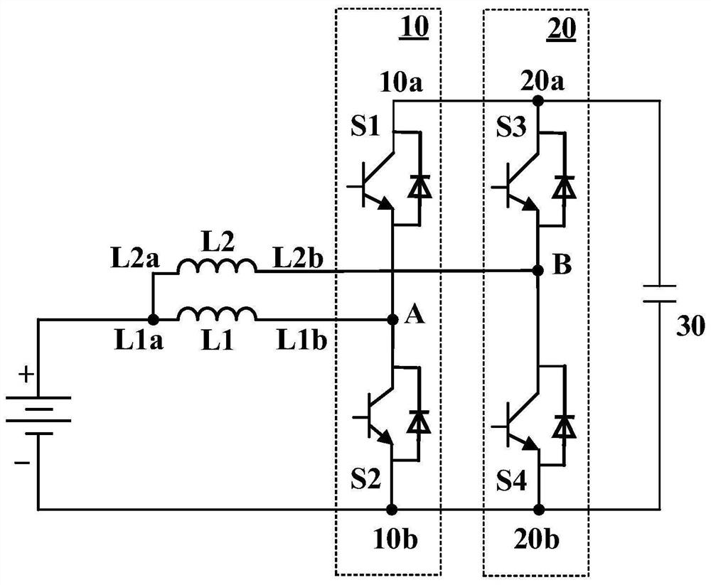
[0074] Wherein, the first end (left end) of the first inductance L1 is connected to the positive pole (+) of the battery; the first end (left end) of the second inductance L2 is connected to the positive pole of the battery; the midpoint A of the first phase bridge arm 10 is connected to The second end (right end) of the first indu...


PUM


Abstract

The invention relates to a battery energy processing device and method and a vehicle. The device comprises a first inductor with the first end connected with the positive electrode of a battery, a second inductor with the first end connected with the positive electrode of the battery, a first phase bridge arm with the midpoint connected with the second end of the first inductor, asecond phase bridge arm with the midpoint connected with the second end of the second inductor, anenergy storage element with the first end connected with the first confluence end and the second end connected with the second confluence end, and a controller configured to control the first phase bridge arm and the second phase bridge arm. Thus, the battery is charged and discharged through the first inductor and the second inductor so as to heat the battery, and the first inductor and the second inductor are in different working states. Therefore, the ripple current in the circuit is small, and the electromagnetic compatibility is good.

Description


Claims


Application Information

Patent Timeline
Owner BYD CO LTD
Why Eureka
Try Eureka