High-precision gyroscope accelerometer floater assembly inertia tensor testing device

An accelerometer and testing device technology, applied in the field of inertial instrument testing, can solve problems such as the inability to calibrate and compensate the inertia tensor of a float assembly, and the inability to accurately calibrate the position of the center of mass of the float assembly, etc., and achieve simple and convenient installation, improved accuracy, and reduced Use the desired effect

Pending Publication Date: 2021-12-03
BEIJING INST OF AEROSPACE CONTROL DEVICES
View PDF0 Cites 2 Cited by
  • Summary
  • Abstract
  • Description
  • Claims
  • Application Information

AI Technical Summary

Problems solved by technology

[0004] At present, there is no effective measurement method to calibrate the inertia tensor (non-linear error) of the gyro accelerometer float assembly. The center of mass of the float assembly is mainly controlled in advance through design, machining and assembly, and it is impossible to accurately calibrate the actual assembly. The position of the center of mass of the float assembly, let alone the calibration and compensation of the inertia tensor of the float assembly

Method used


Image

  • High-precision gyroscope accelerometer floater assembly inertia tensor testing device
  • High-precision gyroscope accelerometer floater assembly inertia tensor testing device
  • High-precision gyroscope accelerometer floater assembly inertia tensor testing device

Examples


Embodiment 1

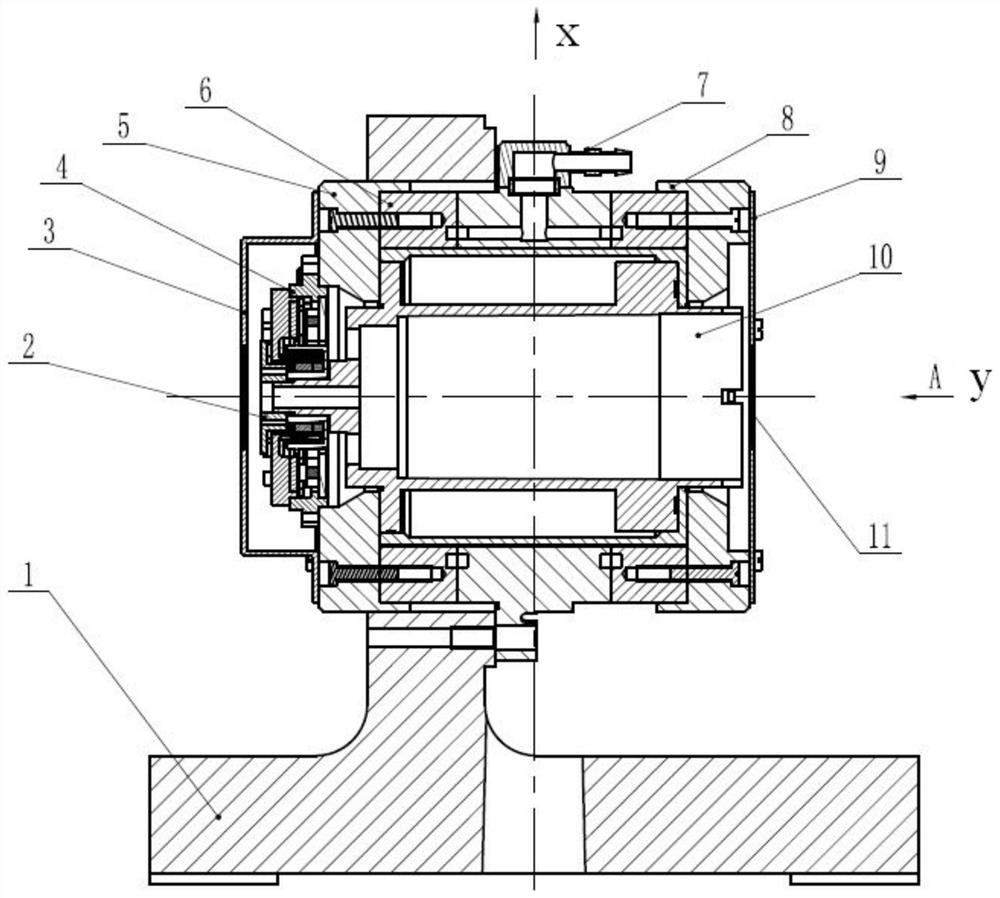
[0046] An inertia tensor testing device for a high-precision gyro accelerometer float assembly, including a mounting plate 1, a balance nut 2, a left cover 3, a combined sensor 4, a left end cover 5, an air bearing sleeve assembly 6, an air nozzle 7, Right end cover 8, right cover 9, rotor body assembly 10, dust screen 11, limit stop nail 12, speed turntable, high-pressure air compression equipment.

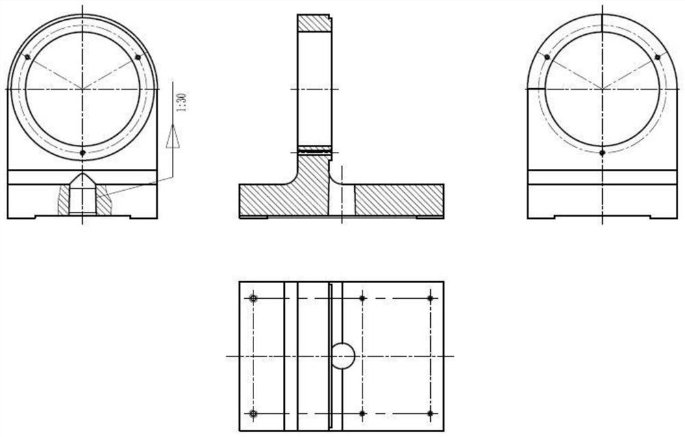
[0047] The mounting plate 1 is a T-shaped base, the right side is the installation reference plane, and there is a through center hole on the reference plane, and there are through thread holes around the through center hole, and they are evenly distributed on concentric circles;

[0048]The through hole at the bottom of the mounting plate has a taper of 1:30 (the large port is downward), and the hole is installed with a round pin with the same taper, so that the center positions between the mounting plate and the speed turntable are coincident, and the installation and operation ...

Embodiment 2

[0065] figure 1 It is an assembly diagram of a gyro accelerometer float assembly inertia tensor test device in an embodiment of the present invention, and the test equipment can be used to calibrate the inertia tensor (non-linear error) of the gyro accelerometer float assembly, which is the Machining and assembly compensation provide the basis. refer to figure 1 and figure 2 , a test device for a gyro accelerometer float assembly provided in this embodiment, including a mounting plate 1, a balance nut 2, a left cover 3, a combined sensor 4, a left end cover 5, an air bearing sleeve assembly 6, and an air nozzle 7 , Right end cover 8, right cover 9, rotor body assembly 10, dust screen 11, limit stop nail 12, speed turntable, compressed air source equipment.

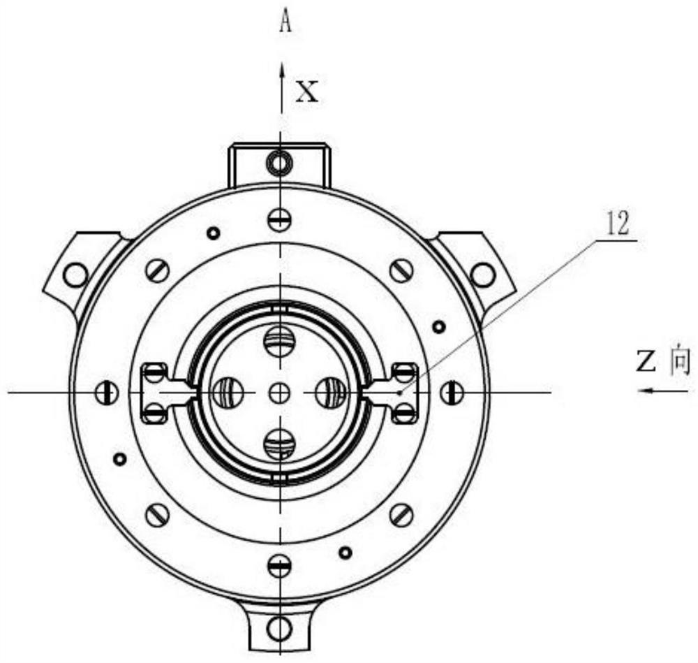
[0066] Such as image 3 As shown, the mounting plate is a T-shaped base, the right side is the installation reference plane, and there is a through central round hole inside the reference plane, and there are 3 small ...


PUM


Abstract

The invention discloses a high-precision gyroscope accelerometer floater assembly inertia tensor testing device. The testing device comprises a rotor body assembly, an air bearing sleeve assembly used for supporting a rotor body, a combined sensor, a balance nut, a left end cover, a right end cover, a limiting blocking nail, a left cover, a right cover, a dust blocking net and a mounting disc. A floater assembly of a gyro accelerometer is placed in the rotor assembly; the rotor assembly is placed in the air bearing sleeve assembly; a charging connector is mounted on the side surface of a bearing sleeve, and the rotor assembly is supported by a high-pressure gas to reduce the frictional resistance moment; the left/right end cover plays a role in supporting the rotor assembly, the stator of a function combined sensor is installed on the left end cover, and the rotor is installed on the rotor assembly. The function combined sensor not only can collect the rotation angle position information of the floater assembly, but also can provide the balance torque; the air bearing sleeve assembly is fixed on the mounting disc through a flange; and a assembly comprising the mounting disc is fixed on a rate turntable to realize a rotating state.

Description

technical field [0001] The invention relates to a high-precision gyro accelerometer float component inertia tensor testing device, which is used for inertia tensor calibration and precision testing of the gyro accelerometer float component, and belongs to the field of inertial instrument testing. Background technique [0002] With the continuous development and application of inertial technology, the precision requirements of the inertial platform navigation system are getting higher and higher. As an important part of the inertial platform navigation system, the gyro accelerometer is also moving towards higher precision, longer life and high reliability. Goal forward. Pendulum Integral Gyro Accelerometer (PIGA) is the core instrument in the high-precision inertial navigation system. With the continuous improvement of PIGA accuracy, the influence of its nonlinear error becomes more and more significant, which has become the bottleneck restricting the further improvement of t...

Claims


Application Information

Patent Timeline
Patent Type & Authority Applications(China)
IPC IPC(8): G01C25/00
CPCG01C25/005
Inventor 凌林本朱宇王琮李亮孙文利牛文韬周晓俊石星烨靖征王昕李刚霍旭霞
Owner BEIJING INST OF AEROSPACE CONTROL DEVICES
Why Eureka
Try Eureka