Household intelligent supervision system
A monitoring system and intelligent technology, applied in general control systems, control/regulation systems, instruments, etc., can solve problems such as single function, non-intelligent electrical control, and lack of home environment safety detection, etc., to achieve a good signal effect
- Summary
- Abstract
- Description
- Claims
- Application Information
AI Technical Summary
Problems solved by technology
Method used
Image
Examples
Embodiment 2
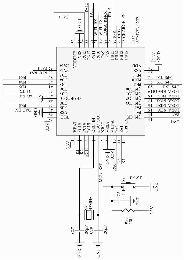
[0035] Example 2, such as figure 1 As shown, the crystal oscillator S2 is connected between the 5 and 6 pins of the chip U15, and the two ends of the crystal oscillator S2 are grounded through the capacitors C27 and C28 respectively, and the first lead of the 7 pins of the chip U15 is grounded through the button S3. The second lead is grounded through the capacitor C34, and the third lead is connected to 3.3V voltage through the resistor R23. The model of the chip U15 is STM32L412T8.
[0036] STM32L412T8 is a MCU chip with low power consumption and multi-channel communication interface. The button S3 is a reset button, which is used to reset the main control chip.
Embodiment 3
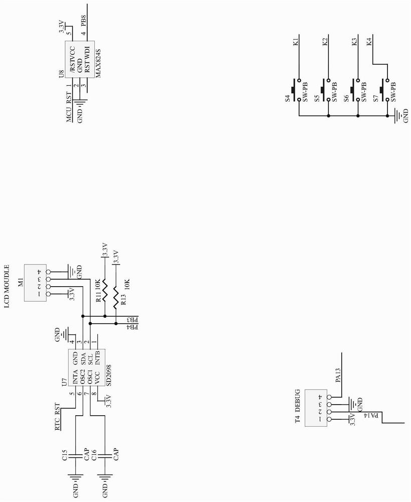
[0037] Example 3, such as Figure 2-3 As shown, the peripheral circuit includes a time circuit, a display circuit, a watchdog circuit, a DEBUG circuit and a button circuit, and the time circuit includes a chip U7, and pins 2, 3 and 5 of the chip U7 are respectively connected to the chip The 40, 39 and 38 pins of U15, the pull-up resistors R13 and R11 are respectively arranged at the 40 and 39 pins of the chip U15, the model of the chip U7 is SD2098, and the display circuit includes a display interface M1, so The 2 and 3 pins of the display interface M1 are respectively connected to the 40 and 39 pins of the chip U15, and the watchdog circuit includes a chip U8, and the 1 and 4 pins of the chip U8 are connected to the chip U15 respectively. 7 and 45 pins, the model of the chip U8 is MAX824S, the DEBUG circuit includes an interface T4, the 2 and 4 pins of the interface T4 are respectively connected to the 37 and 34 pins of the chip U15, and the button circuit It includes button...
Embodiment 4
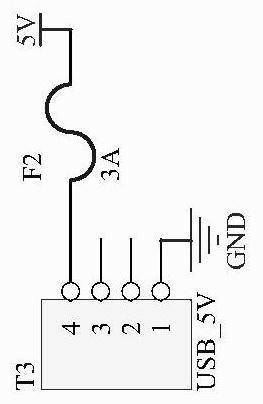
[0039] Example 4, such as image 3 As shown, the power supply circuit includes an interface T3, the 1 pin of the interface T3 is grounded, and the 4 pins are connected to a 5V voltage through the fuse F2; the lithium battery protection circuit includes a chip U3, and the 5 pins of the chip U3 are The first lead is connected to the negative pole of the battery BT1 through the capacitor C6, the second lead is connected to the first end of the fuse F1 through the resistor R1, the second end of the fuse F1 is connected to the positive pole of the battery BT1, and the 6 pins of the chip U3 Connect the negative pole of the battery BT1, the 4 pins are connected to the negative pole of the battery BT1 through the capacitor C8, the 1 pin is connected to the grid of the MOS transistor Q2, the 3 pins are connected to the grid of the MOS transistor Q3, the MOS transistor Q2 The source is connected to the negative pole of the battery BT1, the drain is connected to the drain of the MOS tran...
PUM
 Abstract
Description
Claims
Application Information
 - R&D
- Intellectual Property
- Life Sciences
- Materials
- Tech Scout
- Unparalleled Data Quality
- Higher Quality Content
- 60% Fewer Hallucinations
Browse by: Latest US Patents, China's latest patents, Technical Efficacy Thesaurus, Application Domain, Technology Topic, Popular Technical Reports.
© 2025 PatSnap. All rights reserved.Legal|Privacy policy|Modern Slavery Act Transparency Statement|Sitemap|About US| Contact US: help@patsnap.com


