Forced air cooling type heat dissipation case

A forced air cooling, chassis technology, applied in cooling/ventilation/heating transformation, power electronics modification, electrical components, etc., can solve the problems of heavy weight, failure of the chassis and radiator to form a heat transfer path, and reduced air cooling effect. , to enhance durability, improve heat dissipation efficiency and heat dissipation effect, and reduce airflow resistance

Pending Publication Date: 2021-12-03
GUIYANG AVIATION MOTOR
0 Cites 2 Cited by

AI-Extracted Technical Summary

Problems solved by technology

[0003] The traditional chassis and radiator are independent structures, increasing the number of installed structural parts, making it impossible to form a good heat transfer path between the chassis and radiator, and the weight is heavy
[0004] For elec...

Method used

Please refer to Fig. 1-6, the present invention provides a kind of technical scheme: a kind of forced air-cooled heat dissipation cabinet, comprise casing 1 and be installed in the radiator 4 in casing 1; , the left side panel 13, the right side panel 12, the front panel 14, the rear panel 11 and the cover panel 16 are assembled, and the left side panel 13, the right side panel 12, the front panel 14 and the rear panel 11 are integrated molding structures to form The frame structure of the box body 1, the bottom plate 15 and the cover plate 16 are detachably connected to the frame structure, the bottom plate 15 and the cover plate 16 are designed as detachable structural parts, which is convenient for the installation of the internal fan 5 and the power module 2; The cold heat dissipation chassis mainly adopts a centralized heat dissipation method. Through its own fan 5, it uses the radiator 4 to force air cooling and the natural heat dissipation on the outer surface of the cabinet 1 to dissipate heat from the power module 2, relying on the radiator 4 to achieve heat dissipation, air flow and make For the function of air turning, an inclined surface is provided at the inner step 405 for transition, which reduces airflow resistance, greatly improves the heat dissipation efficiency and heat dissipation effect of the chassis, thereby enhancing the durability of the chassis.
Please refer to Fig. 2, Fig. 4, shown in Fig. 5 and Fig. 6, casing 1 and radiator 4 all adopt antirust aluminum alloy to make, and the outer surface of this casing 1 and radiator 4 is all coated with Plastic-sprayed protective layer, and reinforcing ribs are distributed on the outer wall of the box body 1 at intervals; among them, under the premise of retaining enough reinforcing rib structure, the box body 1 and the structural parts can be punched and grooved on the surface for weight reduction design , to ensure that the strength and height of the air-cooled heat dissipation box 1 are sufficient to meet the purpose of reducing weight at the same time; The airflow inlet 102, the inner side wall of the rear panel 11 is attached to the position of the airflow inlet 102, and the fan 5 is installed; the angle between the air inlet direction of the airflow inlet 102 and the air outlet direction of the airflow outlet 101 is 90 degrees; the transformer 3 is installed on the bottom plate 15 One side wall of the transformer 3 and the power module 2 are fixedly connected to the inner wall of the left side plate 13 .
Please refer to Fig. 4, Fig. 5 and shown in Fig. 6, radiator 4 comprises the hea...

Abstract

The invention discloses a forced air cooling type heat dissipation case which comprises a case body and a radiator installed in the case body. The case body is formed by splicing a bottom plate, a left side plate, a right side plate, a front panel, a rear panel and a cover plate, and a transformer and a power module are mounted on the bottom plate; and the radiator comprises a heat conducting plate which is flatly laid on the power module. According to the forced air cooling type heat dissipation case, the internal power module is cooled through the fan, forced air cooling of the radiator and natural heat dissipation of the outer surface of the case body, the effects of heat dissipation, air flow and air steering are achieved through heat dissipation teeth, heat dissipation straight fins and air flow channels; an inclined face is arranged at the position of an internal step so as to realize transition, the air flow resistance is reduced, the heat dissipation efficiency and the heat dissipation effect of the case are greatly improved, and thus, the durability of the case is enhanced, and long-time use of the air-cooled heat dissipation case is facilitated.

Application Domain

Modifications for power electronics

Technology Topic

EngineeringForced air cooling +7

Image

  • Forced air cooling type heat dissipation case
  • Forced air cooling type heat dissipation case
  • Forced air cooling type heat dissipation case

Examples

  • Experimental program(1)

Example Embodiment

[0021] The following will clearly and completely describe the technical solutions in the embodiments of the present invention with reference to the accompanying drawings in the embodiments of the present invention. Obviously, the described embodiments are only some, not all, embodiments of the present invention. Based on the embodiments of the present invention, all other embodiments obtained by persons of ordinary skill in the art without making creative efforts belong to the protection scope of the present invention.
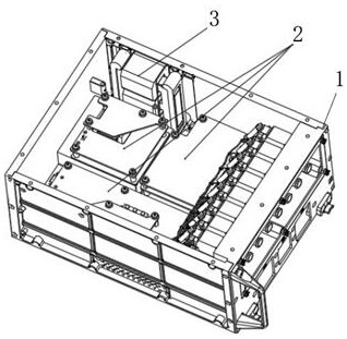
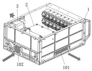
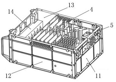
[0022] see Figure 1-6 , the present invention provides a technical solution: a forced air-cooled heat dissipation cabinet, including a cabinet 1 and a radiator 4 installed in the cabinet 1; the cabinet 1 consists of a bottom plate 15, a left side plate 13, and a right side plate 12. The front panel 14, the rear panel 11 and the cover plate 16 are assembled. The left side panel 13, the right side panel 12, the front panel 14 and the rear panel 11 are integrally formed to form the frame structure of the box body 1. The bottom plate 15 and the cover plate 16 are detachably connected to the frame structure, and the base plate 15 and the cover plate 16 are designed as detachable structural parts to facilitate the installation of the internal fan 5 and power module 2; among them, the air-cooled heat dissipation chassis mainly adopts the centralized heat dissipation method , through the built-in fan 5, the power module 2 is radiated by the forced air cooling of the radiator 4 and the natural heat dissipation of the outer surface of the box body 1, and the radiator 4 plays the role of heat dissipation, wind flow and air diversion, and the internal steps are 405 There is a slope for transition, which reduces the airflow resistance, greatly improves the heat dissipation efficiency and heat dissipation effect of the chassis, thereby enhancing the durability of the chassis.
[0023] see figure 2 , Figure 4 , Figure 5 and Image 6 As shown, both the box body 1 and the radiator 4 are made of anti-rust aluminum alloy, the outer surfaces of the box body 1 and the radiator 4 are all coated with a spray-coated protective layer, and the outer walls of the box body 1 are distributed with Reinforcing ribs; among them, on the premise of retaining enough reinforcing ribs, the box body 1 and the structural parts can be perforated and slotted on the surface for weight reduction design, so as to ensure that the strength and height of the air-cooled heat dissipation box 1 are sufficient and meet the requirement of reducing the weight. The purpose of the weight; the surface of the left side plate 13 and the right side plate 12 are provided with an air outlet 101, and the surface of the rear panel 11 is provided with an air inlet 102, and the inner wall of the rear panel 11 is attached to the air inlet 102 A fan 5 is installed on the position; the angle between the air inlet direction of the air inlet 102 and the air outlet direction of the air outlet 101 is 90 degrees; the transformer 3 and the power module 2 are installed on the bottom plate 15, and the side wall of the transformer 3 is fixedly connected to the left side On the inner wall of the plate 13.
[0024] Among them, the plastic spraying protective layer refers to the use of an electrostatic generator to charge the plastic powder, which is a protective layer formed by spraying the plastic powder on the parts to effectively protect the box body 1 and the radiator 4. To prolong the service life of the air-cooled heat dissipation chassis.
[0025] see image 3 As shown, the overall shape of the cover plate 16 and the bottom plate 15 is a rectangle or a rounded rectangle structure, the top edge of the cover plate 16 is equipped with an upper conductive sealing strip 1601, and the top edge of the bottom plate 15 is equipped with a lower conductive sealing strip 1501; through the upper conductive sealing strip 1601 and the lower conductive sealing strip 1501, the joint surface of the bottom plate 15, the cover plate 16 and the frame structure can be sealed, so as to increase the firmness of the overall structure of the air-cooled heat dissipation chassis and prolong the heat dissipation The service life of the chassis.
[0026] see Figure 4 , Figure 5 and Image 6 As shown, the heat sink 4 includes a heat conduction plate 401 installed on the power module 2 , heat dissipation straight fins 404 installed at intervals on the top of the heat conduction plate 401 , and obliquely installed on the top of the heat conduction plate 401 close to the inner wall of the right side plate 12 The heat dissipation teeth 402, the gap between the adjacent heat dissipation straight fins 404 form the airflow channel 403 connected with the airflow outlet 101; the top middle section of the heat conduction plate 401 is provided with a step 405, and the left and right sides of the step 405 are slope structures; Wherein, the step 405 on the heat conduction plate 401 adopts a slope transition to reduce the resistance of the airflow, so that the heat sink 4 can replace the heat in the box body 1 with the outside air, so as to achieve the effect of cooling and heat dissipation; The sheet 404 can increase the circulation of the cooling air, reduce the accumulation of hot air in the radiator 4, and ensure that the transformer 3 achieves the proper heat dissipation effect.
[0027] It should be noted that the top surface of the power module 2 is equipped with an aluminum substrate assembled with a heat conduction plate 401, through the heat conduction of the aluminum substrate, the heat on the power module 2 is conducted to the radiator 4, and most of the heat is driven by the fan 5. The air is taken out by convection, that is, the outside air enters the box 1 through the airflow inlet 102 and the fan 5 and is discharged along the airflow channel 403 to the airflow outlet 101 to realize air convection, and part of the heat is conducted to the radiator 4 again. The heat dissipation is carried out on the cabinet 1, and the transformer 3 directly conducts the heat to the cabinet 1 for heat dissipation due to its high temperature resistance; among them, the cabinet 1 and the radiator 4 are designed in an integrated manner, and the airflow channel 403 and the power module 2 realize Physical isolation, the power module 2 is physically isolated from the external environment.
[0028] The radiator 4 of the present invention and the front panel 14, rear panel 11, left side panel 13 and right side panel 12 of the box body 1 are designed to form a frame structure integrally. Smaller, with good thermal conductivity and excellent corrosion resistance. After spraying plastic on the exposed surface through conductive oxidation, it can have good resistance to salt spray, acidic atmosphere and humid heat environment; the cover plate 16 and the bottom plate 15 are detachable, which is convenient for fans. 5 and the installation of the power module 2, in order to seal, a conductive sealing strip is provided on the cover plate 16 and the bottom plate 15, and the above-mentioned frame structure is shielded and sealed.
[0029] In the present invention, unless otherwise clearly specified and limited, terms such as "installation", "connection", "connection" and "fixation" should be understood in a broad sense, for example, it can be a fixed connection or a detachable connection , or integrated; it can be a mechanical connection; it can be a direct connection or an indirect connection through an intermediary, and it can be the internal communication of two elements or the interaction relationship between two elements. Among them, there are many ways of detachable installation, for example, the way of plugging and buckling can be used, and for example, the way of bolt connection and so on.
[0030] Although the embodiments of the present invention have been shown and described, those skilled in the art can understand that various changes, modifications and substitutions can be made to these embodiments without departing from the principle and spirit of the present invention. and modifications, the scope of the invention is defined by the appended claims and their equivalents.

PUM

no PUM

Description & Claims & Application Information

We can also present the details of the Description, Claims and Application information to help users get a comprehensive understanding of the technical details of the patent, such as background art, summary of invention, brief description of drawings, description of embodiments, and other original content. On the other hand, users can also determine the specific scope of protection of the technology through the list of claims; as well as understand the changes in the life cycle of the technology with the presentation of the patent timeline. Login to view more.

Similar technology patents

Fan blade structure and air conditioner provided with same

PendingCN108507017Alow air resistanceReduce energy consumption
Owner:GREE ELECTRIC APPLIANCES INC OF ZHUHAI

Working Vehicle with HST

ActiveUS20100043419A1improve durabilitysecure safety
Owner:YANMAR POWER TECHNOLOGY CO LTD

Cyclone-type cycling filtration gas-water separation device for fuel cell system

PendingCN110289437Alow air resistanceGood gas permeability
Owner:武汉泰歌氢能汽车有限公司

Linear compressor and lubricating oil pump thereof

InactiveUS20060257275A1improve durabilityadditional processing
Owner:LG ELECTRONICS INC

Drying oven with double air channels for heat setting machine

InactiveCN104420037AEven and smooth airflowlow air resistance
Owner:WUXI CITY HUAYANG DYEING & FINISHING MACHINERY

Production method of high-toughness microcrystal hard alloys

ActiveCN104032153AImprove wear resistance and toughnessImprove durability
Owner:HEYUAN ZHENGXIN HARDMETAL CARBIDE

Floor type air conditioner

InactiveCN102338427Alow air resistanceImprove heat transfer effect
Owner:GREE ELECTRIC APPLIANCES INC OF ZHUHAI

Classification and recommendation of technical efficacy words

  • low air resistance

Cyclone-type cycling filtration gas-water separation device for fuel cell system

PendingCN110289437Alow air resistanceGood gas permeability
Owner:武汉泰歌氢能汽车有限公司

Fan blade structure and air conditioner provided with same

PendingCN108507017Alow air resistanceReduce energy consumption
Owner:GREE ELECTRIC APPLIANCES INC OF ZHUHAI

Drying oven with double air channels for heat setting machine

InactiveCN104420037AEven and smooth airflowlow air resistance
Owner:WUXI CITY HUAYANG DYEING & FINISHING MACHINERY

Floor type air conditioner

InactiveCN102338427Alow air resistanceImprove heat transfer effect
Owner:GREE ELECTRIC APPLIANCES INC OF ZHUHAI
Why Eureka
Try Eureka