Medullary-cavity-pressure-adjustable medulla reaming device for hip joint replacement

An adjustable technology for hip replacement, which is applied in the field of reamers, can solve problems such as joint capsule tissue adhesion, ossification, and knee joint mobility impairment, and achieve the effect of reducing frictional heat generation and lowering temperature

Inactive Publication Date: 2021-12-07
昆明市第一人民医院
View PDF0 Cites 0 Cited by
  • Summary
  • Abstract
  • Description
  • Claims
  • Application Information

AI Technical Summary

Problems solved by technology

[0003] The artificial femoral head needs to be implanted into the autogenous femur. The implantation method is to implant the artificial femoral head handle into the femoral medullary cavity and seal it with bone cement; therefore, the femur needs to be reamed before implantation; and the current reamer Directly reaming the femur will cause the following problems: 1) The expansion of the medullary cavity will increase the intramedullary pressure, which will force the intramedullary fat to squeeze into the Harvard canal, Folkman's canal and nutrient blood vessels, and then pass through the bone cortex and periosteum. The nearby blood vessels enter the circulatory system, and then flow into the lungs, forming a pulmonary embolism; 2) The existing reamer cannot achieve the purpose of flushing the bone debris generated in the medullary cavity while reaming the marrow, and then sucking it out. Residual bone debris can lead to tissue adhesion and ossification in the joint capsule, and cause knee joint mobility impairment; 3) The head of the current reamer is relatively round and blunt, which generates too much heat during reaming and drilling

Method used


Image

  • Medullary-cavity-pressure-adjustable medulla reaming device for hip joint replacement
  • Medullary-cavity-pressure-adjustable medulla reaming device for hip joint replacement
  • Medullary-cavity-pressure-adjustable medulla reaming device for hip joint replacement

Examples


Embodiment 1

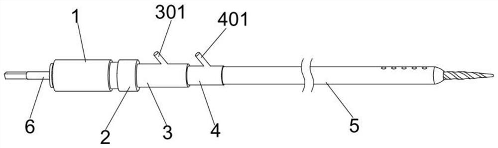
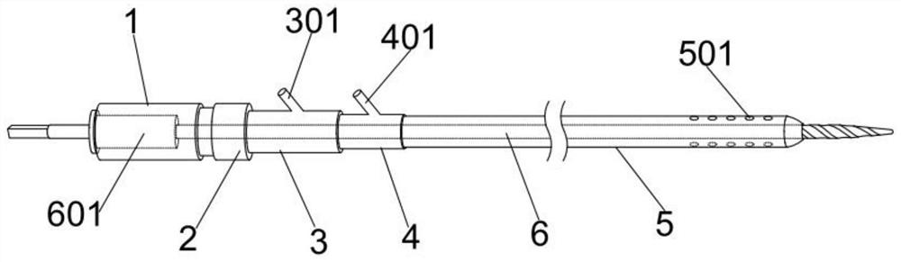
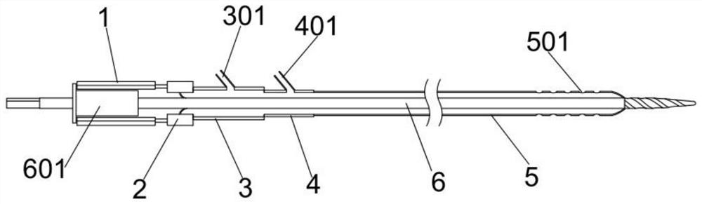
[0035] refer to Figure 1 to Figure 7 As shown, a kind of reamer with adjustable medullary cavity pressure for hip replacement surgery includes: bearing part 1, blocking part 2, negative pressure part 3, flushing part 4, sleeve 5, drill core 6; the bearing The right end of part 1 is transitionally connected to the left end of barrier part 2, the right end of barrier part 2 is connected to the left end of negative pressure part 3, the right end of negative pressure part 3 is connected to the left end of flushing part 4, and the right end of flushing part 4 is detachably connected to the left end of sleeve 5; bearing part 1, barrier part 2. The negative pressure part 3, the flushing part 4, and the sleeve 5 are all hollow structures, and the drill core 6 passes through the opening of the left end of the bearing part 1 through the interior of the above structure and passes through the opening of the right end of the sleeve 5;

[0036] Preferably, the inner wall of the bearing par...


PUM


Abstract

The invention discloses a medullary-cavity-pressure-adjustable medulla reaming device for a hip joint replacement. The medulla reaming device comprises a bearing part, a blocking part, a negative pressure part, a flushing part, a sleeve and a drill core, wherein the right end of the bearing part is in transition connection with the left end of the blocking part, the right end of the blocking part is connected with the left end of the negative pressure part, the right end of the negative pressure part is connected with the left end of the flushing part, and the right end of the flushing part is detachably connected with the left end of the sleeve; and interiors of the bearing part, the blocking part, the negative pressure part, the flushing part and the sleeve are all hollow structures, and the drill core penetrates through the above-mentioned structures from an opening in the left end of the bearing part and penetrates out of an opening in the right end of the sleeve. The pressure in a medullary cavity can be lowered through negative pressure during medulla reaming, then, bone scraps generated in a medulla reaming process are sucked out of the medullary cavity through flushing and negative pressure suction, a drill bit of the medulla reaming device is designed to be sharp, and heat generated in a drilling process is reduced while the requirement on sharpness is met.

Description

technical field [0001] The invention belongs to the field of hip joint replacement surgical instruments, in particular to a reamer for hip joint replacement that can adjust the pressure of the medullary cavity. Background technique [0002] Hip replacement is one of the more common surgical methods in clinical practice, mainly to solve the damage of the hip joint; hip replacement is to remove the femoral head and replace the artificial femoral head, and the acetabular side is ground to remove the proliferative osteophyte tissue and installed Artificial acetabular cup, through artificial femoral head and acetabular cup to form a new joint, called artificial hip joint; [0003] The artificial femoral head needs to be implanted into the autogenous femur. The implantation method is to implant the artificial femoral head handle into the femoral medullary cavity and seal it with bone cement; therefore, the femur needs to be reamed before implantation; and the current reamer Direc...

Claims


Application Information

Patent Timeline
Patent Type & Authority Applications(China)
IPC IPC(8): A61B17/16
CPCA61B17/164A61B17/1668A61B2217/005
Inventor 赵文川陈鸿李瑞宏李彪杨毅刘韦兵王自伟郭艳张正学溪应龙段玉平
Owner 昆明市第一人民医院
Why Eureka
Try Eureka