Small milling machine for workpiece positioning

A milling machine, a small-scale technology, applied in the field of milling machines, can solve the problems of low drilling accuracy and efficiency, narrow working space, etc., and achieve the effects of improving production and processing efficiency, high precision, and small size

Inactive Publication Date: 2021-12-07
CHANGZHOU INST OF MECHATRONIC TECH
View PDF0 Cites 0 Cited by
  • Summary
  • Abstract
  • Description
  • Claims
  • Application Information

AI Technical Summary

Problems solved by technology

According to the coil winding process, the opening must be made during the winding process, such as figure 2 As shown, the conductors show a tendency to open at this time, the distance between the conductors is generally 400mm, and the minimum inner diameter of the conductors is 750mm. Due to the narrow working space on site, the general milling machine equipment on the market cannot solve this problem. less efficient

Method used


Image

  • Small milling machine for workpiece positioning
  • Small milling machine for workpiece positioning
  • Small milling machine for workpiece positioning

Examples


Embodiment Construction

[0036] In order to make the present invention more easily to be clearly understood, the following Examples depending on the particular embodiment and the accompanying drawings, the present invention will be further described in detail.

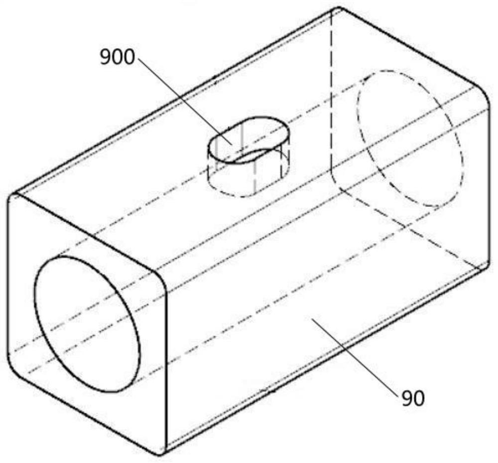
[0037] like figure 1 , 2 Shown, conductor coil 9 in the winding process, the need to open side 90 within the circular outer conductor armor helium racetrack holes 900, but because of site work space is small, the prior art apparatus does not resolve the milling machine class problem.

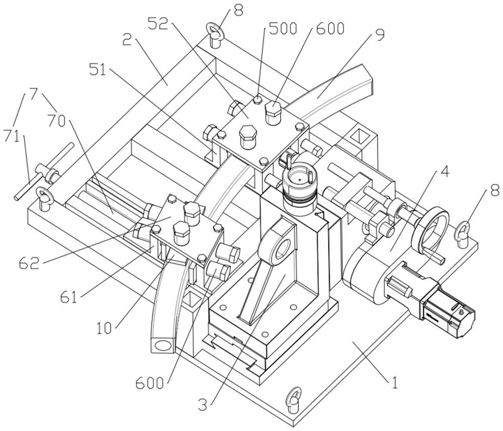
[0038] So, if Figure 3-7 , In the present embodiment, there is provided a small milling machine A work positioning, comprising milling means, the base 1 and the welding line hanging line hanging clamp the front end of the base bracket 2 1, line hanging clamp bracket 2 and base 1 are used alloy steel welding and be annealed, high strength, long life, easy maintenance, greatly reducing the cost. On the clamp bracket 2 is attached to the fixing jig 5 and the movable cl...


PUM


Abstract

The invention discloses a small milling machine for workpiece positioning. The small milling machine comprises a milling machine mechanism, a crane base and a clamp support arranged at one end of the crane base, a fixed clamp and a movable clamp are installed on the clamp support, and the movable clamp is movably installed on the clamp support through a lead screw mechanism; the fixed clamp and the movable clamp are used for clamping a conductor coil, and the movable clamp can move front and back in the Y-axis direction under driving of the lead screw mechanism so as to be matched with the curvature of the conductor coil; the milling machine mechanism is installed on the crane base and used for tapping in the conductor coil winding process. and a plurality of suspension rings are also arranged at the end parts of the crane base and the clamp support. The small milling machine is suitable for machining special workpieces, and compared with existing milling machine equipment, the small milling machine is compact in structure, large in rigidity and high in precision, can meet the working environment requirement of coil winding field tapping, improves the machining precision and efficiency of helium holes, and provides equipment guarantee for superconducting coil helium hole drilling.

Description

Technical field [0001] The present invention relates to the field of milling technology, particularly to small milling A work positioning. Background technique [0002] Currently, in the prior art, the superconducting coil tokamak using conductor wound from CICC, CICC structure refers to a superconducting cable is inserted into the circular outer conductor and then through the armor reduced diameter is formed, and super wire turns during the winding process also requires the molding using supercritical helium forced flow cooling liquid helium is introduced to the interior of the coil, the need to excavate in the racetrack holes helium inside or outside of the coil conductors armor, such as figure 1 . The coil winding process, the opening must be in the winding process, such as figure 2 As shown in this case the conductor presents trends open, the spacing between conductors is usually 400mm, 750mm minimum inner diameter of the conductor, since the small working space field, millin...

Claims


Application Information

Patent Timeline
Patent Type & Authority Applications(China)
IPC IPC(8): B23C1/00B23Q3/00
CPCB23C1/00B23Q3/00
Inventor 许爱华唐悦朱亚军常汪娜刘江蔡福海王行刚
Owner CHANGZHOU INST OF MECHATRONIC TECH
Why Eureka
Try Eureka