Curved surface coating process for electrochromic lens
An electrochromic and electrochromic layer technology, applied in metal material coating process, sputtering plating, ion implantation plating, etc., can solve problems such as inconvenience to use, and achieve simple device, low frequency, and film quality. high effect
- Summary
- Abstract
- Description
- Claims
- Application Information
AI Technical Summary
Problems solved by technology
Method used
Image

Examples
Embodiment 1
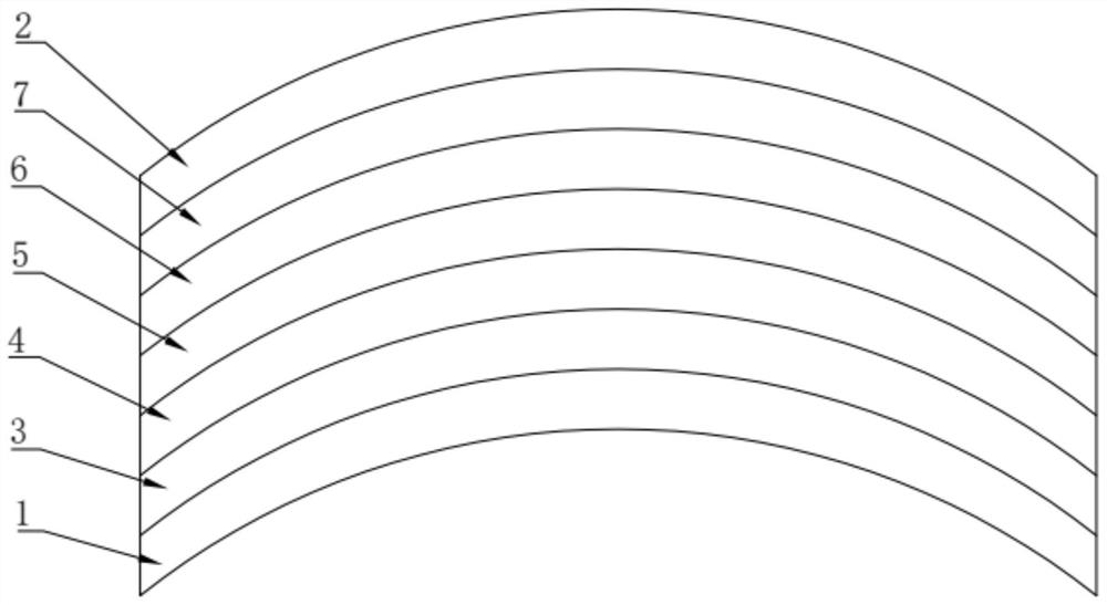
[0037] A curved surface coating process for electrochromic lenses,
[0038] Step 1, heat-bending the substrate 1 and the cover glass 2;
[0039] Step 2, forming an electrochromic coating film on the substrate 1 by magnetron sputtering, including:
[0040] Using intermediate frequency unbalanced magnetron sputtering, the first transparent electrode layer 3 is sprayed on the substrate 1 with an eccentric cylindrical target, the target material is ITO, and at least 5 accompanying plates are sprayed together with the substrate 1 to obtain the first accompanying plating piece;
[0041] The electrochromic layer 4 is sprayed on the first transparent electrode layer 3 by double-target unbalanced magnetron sputtering. The two targets are W and Ti respectively, and the mass ratio of Ti and W in the electrochromic layer 4 is controlled by parameter adjustment. The ratio is 1:10, and the second accompanying sheet is obtained by spraying together with the first accompanying sheet;
[00...
Embodiment 2
[0047] A curved surface coating process for electrochromic lenses,
[0048] Step 1, heat-bending the substrate 1 and the cover glass 2;
[0049] Step 2, forming an electrochromic coating film on the substrate 1 by magnetron sputtering, including:
[0050]Using intermediate frequency unbalanced magnetron sputtering, the first transparent electrode layer 3 is sprayed on the substrate 1 with an eccentric cylindrical target, the target material is ITO, and at least 5 accompanying plates are sprayed together with the substrate 1 to obtain the first accompanying plating piece;
[0051] The electrochromic layer 4 is sprayed on the first transparent electrode layer 3 by double-target unbalanced magnetron sputtering. The two targets are W and Ti respectively, and the mass ratio of Ti and W in the electrochromic layer 4 is controlled by parameter adjustment. The ratio is 1:20, and the second accompanying sheet is obtained by spraying together with the first accompanying sheet;
[005...
Embodiment 3
[0057] A curved surface coating process for electrochromic lenses,
[0058] Step 1, heat-bending the substrate 1 and the cover glass 2;
[0059] Step 2, forming an electrochromic coating film on the substrate 1 by magnetron sputtering, including:
[0060] Using intermediate frequency unbalanced magnetron sputtering, the first transparent electrode layer 3 is sprayed on the substrate 1 with an eccentric cylindrical target, the target material is ITO, and at least 5 accompanying plates are sprayed together with the substrate 1 to obtain the first accompanying plating piece;
[0061] The electrochromic layer 4 is sprayed on the first transparent electrode layer 3 by double-target unbalanced magnetron sputtering. The two targets are W and Ti respectively, and the mass ratio of Ti and W in the electrochromic layer 4 is controlled by parameter adjustment. The ratio is 1:30, and the second accompanying sheet is obtained by spraying together with the first accompanying sheet;
[00...
PUM
 Abstract
Description
Claims
Application Information
 - R&D
- Intellectual Property
- Life Sciences
- Materials
- Tech Scout
- Unparalleled Data Quality
- Higher Quality Content
- 60% Fewer Hallucinations
Browse by: Latest US Patents, China's latest patents, Technical Efficacy Thesaurus, Application Domain, Technology Topic, Popular Technical Reports.
© 2025 PatSnap. All rights reserved.Legal|Privacy policy|Modern Slavery Act Transparency Statement|Sitemap|About US| Contact US: help@patsnap.com