Improved endometrial hemostasis device

An improved, uterine technology, applied in the field of improved uterine inner wall hemostatic device, can solve the problems of inability to evaluate the hemostatic effect, inability to judge, and inability to spray liquid medicine, etc., so as to avoid hemostasis failure or medical accident, avoid waste of liquid medicine, avoid Effects of failed hemostasis

Inactive Publication Date: 2021-12-10
王政乾
View PDF1 Cites 2 Cited by
  • Summary
  • Abstract
  • Description
  • Claims
  • Application Information

AI Technical Summary

Problems solved by technology

[0004] However, it is well known that the inner cavity of the uterus is an inverted triangle, and the inflated shape of the conventional spherical balloon is quite different from the shape of the inner cavity of the uterus. Therefore, when the inner wall of the uterus is squeezed, different parts of the uterine wall will bear different pressures, such as , the pressure on some parts is too large, even exceeding the limit of the patient, and another part of the uterine wall has not fully contacted the air bag; big bleeding
[0005] In view of the above problems, the description of the patent document mentions that the shape of the airbag can also be made to fit the shape of the uterine cavity. For this statement, the applicant also consulted some other similar patent documents, and there are more or less similar expression, but they all have one thing in common: the structure of the airbag that fits the shape of the uterine cavity is not given, so people can only think of making a triangular-like airbag with the means of the existing technology
[0006] According to the principle of pressure, even if it is a triangular airbag, when it is inflated, due to the large upper and lower areas, the relative pressure is relatively large, which will cause the upper and lower sides to over-inflate and bulge, thus excessively squeezing the front and rear walls of the uterus, and at the same time The side wall is excessively torn, this method obviously does not solve the above technical problems
However, the important basis why the above-mentioned patent documents can play a hemostatic effect is that the shape of the air bag can be adapted to the uterine cavity, otherwise, on the one hand, there is a risk that the patient cannot bear it or the wound is torn; The defect of uneven liquid distribution
[0007] In addition, in the existing patent documents of this type, hemostasis in the form of a balloon is a hemostasis in a blind state, which cannot accurately determine the position of the bleeding wound in the uterine cavity, nor can it be targeted at the bleeding wound In addition, it is impossible to evaluate the effect of the hemostasis process, resulting in the waste of liquid medicine and low therapeutic effect.

Method used


Image

  • Improved endometrial hemostasis device
  • Improved endometrial hemostasis device
  • Improved endometrial hemostasis device

Examples


Embodiment 1

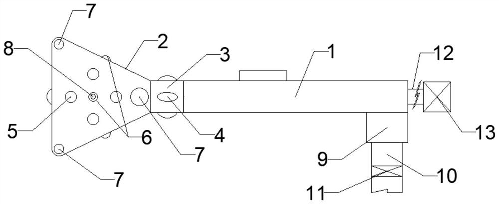
[0029] An improved hemostatic device for the inner wall of the uterus, such as Figure 1-4As shown, it includes an elastic cover body 2, a handle 1, a controller (not shown in the figure), and a computer (not shown in the figure), which are triangular in plan. One apex of the elastic cover body 2 is connected to the handle 1 , the handle 1 is a tubular structure, and a cervical support tube 3 is also connected between the handle 1 and the elastic cover body 2. The outer surface of the side wall of the cervical support tube 3 is evenly distributed with several supports 4. The top rod-shaped airbag 16 and the waist rod-shaped airbag 17 are respectively arranged on the front end and the waist both sides in the elastic cover body 2, and the two ends of the top rod-shaped airbag 16 and the waist rod-shaped airbag 17 are fixed to the inner surface of the elastic cover body 2 respectively. Connecting, when the top rod-shaped air bag 16 and the waist rod-shaped air bag 17 are inflated...

Embodiment 2

[0037] This embodiment is an improvement made on the basis of Embodiment 1, specifically:

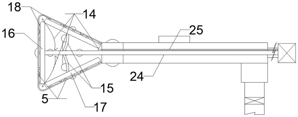
[0038] Such as figure 2 As shown, the two waist rod-shaped airbags 17 are respectively connected to the first gas delivery tube 24 through the first sub-connecting hose 15; the first gas delivery tube is an elastic rubber tube, and the first gas delivery tube The front end of the tube is connected with the middle part of the top rod-shaped air bag 16 .

[0039] In this embodiment, when the three rod-shaped airbags are contracted, the elastic cover is tightened around the end of the first gas delivery tube 24 to facilitate entry into the cervix.

Embodiment 3

[0041] This embodiment is an improvement made on the basis of Embodiment 2, specifically:

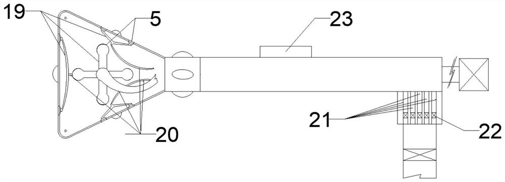
[0042] Such as figure 1 , 4 As shown, the corners of the upper and lower ends of the elastic cover 2 are respectively provided with support airbags 7, and the support airbags 7 are connected with the second gas through the second sub-connecting hose 14 that runs through the inside of the elastic cover 2. The delivery tube 25 , the second gas delivery tube 25 runs through the cervical support tube 3 and the end of the handle 1 to connect with the gas pressure regulating mechanism 13 .

[0043] In this embodiment, when the elastic cover is fully opened due to the inflation of the three rod-shaped airbags, the elastic cover can be supported in the inner cavity of the uterus by inflating the six support airbags 7, and the support airbags 7 make the elastic cover fully open. Positioning is conducive to the stability of the spraying range, and at the same time, the distance between the spra...


PUM


Abstract

The utility model discloses an improved endometrial hemostasis device, and relates to the technical field of gynecological hemostasis devices. The improved endometrial hemostasis device comprises an elastic cover body, a handle, a controller, a computer, a cervix uteri supporting pipe, a top rod-shaped air bag, a waist rod-shaped air bag, an atomized liquid medicine spraying hole, a liquid medicine conveying hose, a liquid medicine conveying header pipe, a first connector, a liquid medicine conveying header pipe, a flow pump, an atomized liquid medicine supply device, a first gas conveying pipe, a gas pressure adjusting mechanism, a spherical flow guide cover, a micro digital camera, a first solenoid valve and a control panel. The invention provides an air bag structure adaptive to uterine cavity, so that targeted hemostasis can be realized, and the hemostasis efficiency and the hemostasis effect are effectively improved.

Description

technical field [0001] The invention relates to the technical field of gynecological hemostatic devices, in particular to an improved uterine inner wall hemostatic device. Background technique [0002] Some devices for gynecological uterine hemostasis are disclosed in the patent literature. Air bags are usually used. Anti-inflammatory and hemostatic drugs are coated on the surface of the air bags. However, in the state of uterine bleeding, it is difficult to control the amount of hemostatic drugs on the surface of the balloon. If the local drug dosage is insufficient or the drugs on the outer surface of the balloon cannot contact the uterine wall due to the special structure of the uterine inner wall, it is easy to cause hemostasis failure. In addition, after the balloon is inflated, it will press the inner wall of the uterus. If the pressure is too high, it will easily lead to increased bleeding, and due to the obstruction of the balloon itself, blood will easily accumulate...

Claims


Application Information

Patent Timeline
Patent Type & Authority Applications(China)
IPC IPC(8): A61B17/12A61B17/42A61B17/00A61M11/00A61M25/10A61M31/00
CPCA61B17/12A61B17/42A61B17/00234A61M31/00A61M11/00A61M25/1002A61M25/1011A61B2017/12004A61B2017/4216A61M2025/1015A61M2210/1433A61M2205/583A61M2210/005
Inventor 不公告发明人
Owner 王政乾
Why Eureka
Try Eureka