Fan-shaped cylinder assembly of reforming reactor

A technology of reforming reactors and fan-shaped cylinders, applied in chemical instruments and methods, chemical/physical processes, etc., can solve the problems of less flow of raw materials, increased catalyst dust, and increased catalyst consumption, so as to reduce operating investment costs , Eliminate flow dead zone, reduce filling effect

Pending Publication Date: 2021-12-10
BC P INC CHINA NAT PETROLEUM CORP +1
View PDF0 Cites 0 Cited by
  • Summary
  • Abstract
  • Description
  • Claims
  • Application Information

AI Technical Summary

Problems solved by technology

The above-mentioned fan-shaped cylinder assembly has been operated at high temperature for a long time. Factors such as high-temperature thermal expansion, sudden pressure drop, and operation fluctuation are the tests for the fan-shaped cylinder structure. During the operation of the reforming reactor, if the fan-shaped cylinder assembly is dented, cracked, or Such problems will lead to increased catalyst consumption, partial catalyst fluidization, and increased catalyst dust, which will directly affect the production efficiency of the reforming unit, affect the quality of the product and the safe and stable operation of downstream units, and are not conducive to the long-term operation of the unit
[0004] However, because the fan-shaped cylinders are arranged inside the reactor, there are certain gaps between adjacent fan-shaped cylinders, and these gaps form the flow dead zone of the catalyst. These flow dead zones not only make the flow rate of the raw material less, but also increase the Catalyst loading increases operating investment costs

Method used


Image

  • Fan-shaped cylinder assembly of reforming reactor
  • Fan-shaped cylinder assembly of reforming reactor
  • Fan-shaped cylinder assembly of reforming reactor

Examples


Embodiment Construction

[0055] To make the objectives, technical solutions, and advantages of the present disclosure clearer, the following with reference to embodiments of the present application will be described in further detail.

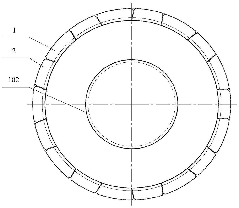
[0056] figure 1 It is a structural diagram of a fan assembly provided a cylindrical reforming reactor according to the present embodiment of the application;

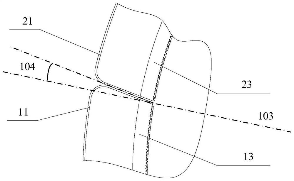
[0057] figure 2 Is a diagram showing the sector structure of a cartridge assembly of the contact surface provided by the embodiment of the present application; see figure 1 and figure 2 The sector tube assembly comprising: at least two female sector tube 1 and at least two convex cylinder sectors 2; said concave cylindrical sector 1 and the sector of the convex cylinder 2 are arranged at intervals, a cylindrical shape, the adjacent concave cylindrical sector 1 and the contact surface between the convex cylindrical sector close contact, and the angle 104 between the contact surface 103 of the radial line segment of...


PUM

PropertyMeasurementUnit
Heightaaaaaaaaaa

Abstract

The invention relates to a fan-shaped cylinder assembly of a reforming reactor, and belongs to the technical field of reforming reaction equipment. According to the fan-shaped cylinder assembly provided by the invention, at least two concave fan-shaped cylinders and at least two convex fan-shaped cylinders are arranged, the concave fan-shaped cylinders and the convex fan-shaped cylinders are arranged at intervals, and the contact surfaces of the adjacent concave fan-shaped cylinders and convex fan-shaped cylinders are tightly attached, so that no gap exists between the adjacent fan-shaped cylinders. The included angle between each contact surface and the radial line of the fan-shaped cylinder assembly is 8-20 degrees, so that the extension direction of the contact surfaces is inconsistent with the flowing direction of a catalyst, and the possibility that the catalyst flows into the contact surfaces is reduced, the flowing dead zone of the catalyst is eliminated, the flowability of raw materials and the catalyst is enhanced, the filling amount of the catalyst is reduced, and the operation investment cost is further reduced. Meanwhile, the internal structures of the concave fan-shaped cylinders and the convex fan-shaped cylinders are welded, so that the structural strength of the fan-shaped cylinder assembly is high, and the service life of the fan-shaped cylinder assembly is long.

Description

Technical field [0001] Technical Field The present application relates to the reforming reaction apparatus, and particularly relates to a fan assembly for a cylindrical reforming reactor. Background technique [0002] Reforming the reforming reactor is a continuous reactor important equipment, the reforming reactor core portion of the inner tube and comprises a central sector tube assembly. Common continuous reforming catalyst in the reactor under the action of gravity, the top of the catalyst hopper through the catalyst feed pipe, the top-down flow through the reactor bed. [0003] Important sector tube member is a continuous reforming apparatus inside the reactor reforming apparatus, mounted on the inner wall surface of the reforming reactor, the reforming reactor pipe with the use, for isolation of the catalyst, so that a uniform distribution of the process medium, diameter through the catalyst bed, the reaction product was out of the reactor into the central tube. Sector tube...

Claims


Application Information

Patent Timeline
IPC IPC(8): B01J8/12
CPCB01J8/12
Inventor 刘伟吴智莹魏治中刘文庄剑锋许佳崔保林
Owner BC P INC CHINA NAT PETROLEUM CORP
Why Eureka
Try Eureka