
Differential type mold locking pressure relief oil way for two-plate injection molding machine

A pressure relief oil circuit, differential type technology, applied in the field of differential clamping pressure relief oil circuit, can solve the problems of obvious oil return noise, mold breaking failure, loud secondary pressure relief sound, etc., and achieve the pressure relief process. The effect of stable, good oil cleanliness and low oil return noise

Pending Publication Date: 2021-12-10
NINGBO ZHAFIR PLASTICS MACHINERY
View PDF0 Cites 2 Cited by
  • Summary
  • Abstract
  • Description
  • Claims
  • Application Information

AI Technical Summary

Problems solved by technology

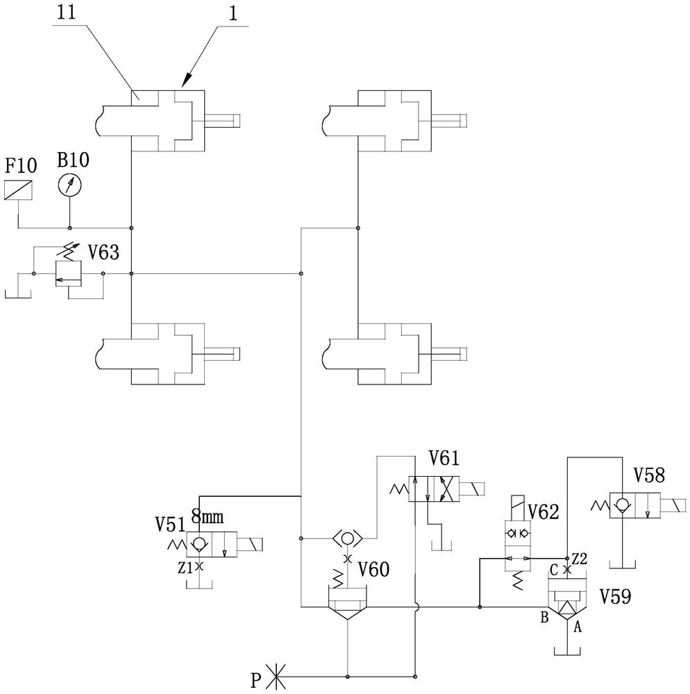
[0005] 1) In order to slow down the opening speed of the spool of the oil return cartridge valve V59, a damper Z2 is added to the C port of the oil return cartridge valve V59, and the oil return cartridge valve V59 is equipped with a cushioning spool. The damping Z2 needs to take into account the mold breaking speed at the same time (the smaller the damping Z2 is, the better when the mold is clamped to release the pressure, and the larger the damping Z2 is, the better when the mold is broken), so the selection of the damping Z2 should not be too small. If the damping Z2 is too small, the weather will be cold When the oil is viscous, the hole of damping Z2 is easy to block, which will cause difficulty in oil circulation, which will cause slow mold breaking speed or even failure of mold breaking; in addition, the actual measurement effect of the cushioning valve core is also very limited, so although the mold clamping process in this process The pressure has dropped, but due to the large flow rate, the spool opening speed of the oil return cartridge valve V59 is still relatively fast, and the oil impact during this stage of pressure relief is still relatively large;
[0006] 2) Since the two-stage mold clamping and pressure relief are based on the product process, there are many uncertainties. For example, some product processes require constant pressure holding, some products are finished with injection and pressure holding, and cooling is also over. The mold clamping pressure should not drop too much, etc. These circumstances lead to the unusable early pressure relief function, or occupy the production cycle after use, or the second pressure relief sound is still loud after use, resulting in the two-stage pressure relief cannot fully cover the application;
[0007] 3) The final large-flow pressure relief in the two-stage mold clamping pressure relief is still directly returned to the oil tank, lacking energy absorption, the vibration caused by the impact is still relatively obvious, the oil return noise generated is still relatively obvious, and the oil in the oil tank is also clean. poor

Method used


Image

  • Differential type mold locking pressure relief oil way for two-plate injection molding machine
  • Differential type mold locking pressure relief oil way for two-plate injection molding machine
  • Differential type mold locking pressure relief oil way for two-plate injection molding machine

Examples


Embodiment Construction

[0023] The present invention will be further described in detail below in conjunction with the accompanying drawings and embodiments.

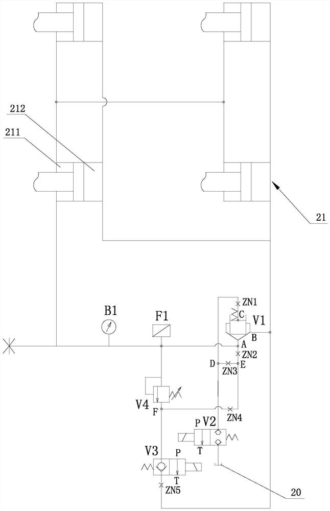
[0024] The present invention proposes a differential clamping pressure relief oil circuit for a two-platen injection molding machine, such as figure 2As shown, it includes a cartridge valve V1 with a spool of 1:1, a first two-position two-way electromagnetic reversing valve V2, a second two-position two-way electromagnetic reversing valve V3 and a fuel tank 20; the bottom of the cartridge valve V1 The working oil port, i.e. port A, communicates with the clamping cavity 211 of the clamping cylinder 21 and the side working oil port of the cartridge valve V1, i.e. port B, communicates with the mold breaking cavity 212 of the clamping cylinder 21 to form the main channel oil circuit; When the electromagnet of the two-position two-way electromagnetic reversing valve V3 is energized, the pilot port of the cartridge valve V1, that is, the C port, pa...


PUM


Abstract

The invention discloses a differential type mold locking pressure relief oil way for a two-plate injection molding machine. The differential type mold locking pressure relief oil way comprises a cartridge valve, two two-position two-way electromagnetic directional valves and an oil tank, wherein a bottom working oil port of the cartridge valve communicates with a mold locking cavity, a side edge working oil port of the cartridge valve communicates with a mold breaking cavity to form a main channel oil way, when mold locking acts and an electromagnet of a second two-position two-way electromagnetic directional valve is electrified, a pilot port of the cartridge valve reaches a side working oil port of the cartridge valve through a first damper, a third damper, a fourth damper and a fifth damper, and a bottom working oil port of the cartridge valve reaches the side working oil port of the cartridge valve through a second damper, the fourth damper and the fifth damper, the cartridge valve is slowly opened to realize differential mold locking pressure relief, and during mold breaking action, when the electromagnet of the first two-position two-way electromagnetic directional valve is electrified, the pilot port of the cartridge valve reaches the oil tank through the first damper, so that the cartridge valve is quickly opened to realize differential mold breaking. The differential type mold locking pressure relief oil way has the advantages that the mold locking and pressure relief process is stable, the mold breaking action is considered, and the oil cleanliness is good.

Description

technical field [0001] The invention relates to a mold clamping pressure relief technology for an injection molding machine, in particular to a differential mold clamping pressure relief oil circuit for a two-platen injection molding machine. Background technique [0002] In the two-platen injection molding machine, the basic actions are as follows: mold clamping - brake - high pressure mold clamping - injection - injection - holding pressure - premolding - ejection - cooling - mold clamping pressure relief - mold breaking - gate opening - opening Die-Pickup. Clamping pressure relief action is the process of releasing the oil in the clamping cavity of the clamping cylinder from high pressure to low pressure. Shock occurs in the oil zone, which will cause vibration and then oil return noise. [0003] In order to solve the above problems, people in the industry have proposed a clamping pressure relief oil circuit. figure 1 An existing clamping pressure relief oil circuit is...

Claims


Application Information

Patent Timeline
Patent Type & Authority Applications(China)
IPC IPC(8): B29C45/82B29C45/67
CPCB29C45/82B29C45/67
Inventor 周东海李炯饶乐庆周健荣魏嘉勇
Owner NINGBO ZHAFIR PLASTICS MACHINERY
Learn More