Energy-saving and environmental-friendly battery jar conveyor and working method thereof

An energy saving, environmental protection, conveyor technology, applied in conveyors, conveyor objects, circuits, etc., can solve the problems of large and difficult centralized charging, inability to flexibly use the volume of the conveyor, etc., to achieve flexible use, strong applicability, and convenient use. Effect

Inactive Publication Date: 2021-12-10
ANHUI KAIJIE MACHINERY MFG
View PDF1 Cites 2 Cited by
  • Summary
  • Abstract
  • Description
  • Claims
  • Application Information

AI Technical Summary

Problems solved by technology

[0005] The invention drives the motor of the conveyor to rotate and the oil cylinder to go up and down through the electric power in the power battery box, which not only realizes the height adjustment and conveying operation of the conveyor, but also avoids the limitation of power components such as fixed power supply or cables, so that the applicability of the conveyor is improved. Strong, energy-saving and environmentally friendly. In the present invention, the snap ring and the connecting rod mechanism are connected with the push rod. Only by turning and unfolding the push rod, the unlocking of the power battery box locking mechanism and the extension of the universal wheel can be realized. The operation is convenient. , There is a fan above the power battery box, which can continuously blow the power battery box. It can not only clean up the debris in the power battery box area, but also accelerate the heat dissipation of the power battery box through the continuous flow of airflow, improving the efficiency of the power battery. The stability and safety of the box during use solves the problem that the conveyor cannot be used flexibly due to the influence of factors such as fixed power supply during use, and the problem that the conveyor is too large to be charged centrally

Method used


Image

  • Energy-saving and environmental-friendly battery jar conveyor and working method thereof
  • Energy-saving and environmental-friendly battery jar conveyor and working method thereof
  • Energy-saving and environmental-friendly battery jar conveyor and working method thereof

Examples


Embodiment 1

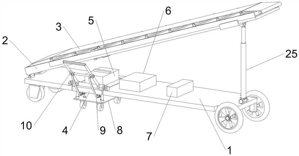
[0040] see Figure 1-Figure 2 As shown in the figure, an energy-saving and environment-friendly battery conveyor includes a bottom plate 1. Universal wheels are installed on the bottom of the bottom plate 1, and the universal wheels have a brake function. By stepping on the brakes, the universal wheels can be locked and fixedly transported. The position of the machine, the upper part of the bottom plate 1 is connected with the feeding plate 2, and the upper part of the feeding plate 2 is connected with the conveyor belt 3. The connection between the feeding plate 2 and the bottom plate 1 is through the oil cylinder 25. The oil cylinder 25 can be extended and then shortened. The output end of 25 is fixed on the lower surface of the loading plate 2, and the bottom end of the oil cylinder 25 can rotate on the base plate 1, and the oil cylinder 25 is driven by the hydraulic power box 7, and the hydraulic power box 7 is fixedly installed on the upper surface of the base plate 1, and...

Embodiment 2

[0043] The conveyor is powered by batteries. When charging the conveyor, a separate power battery box 5 is used, so that the battery box can be disassembled from the conveyor, so that the entire device does not need to be moved to the charging area when charging. convenient.

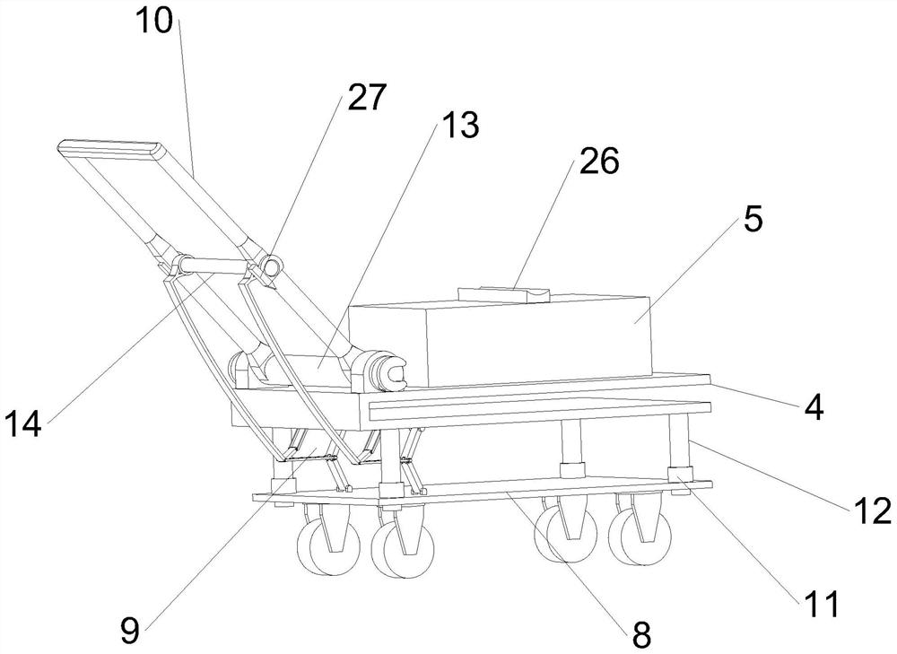
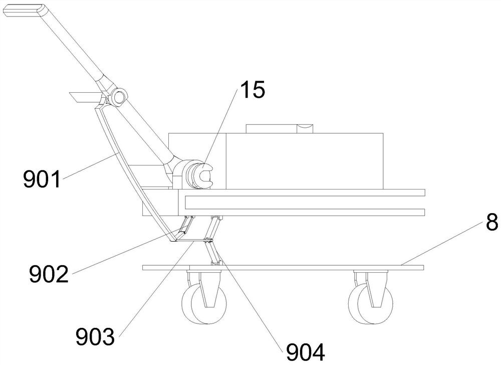
[0044] see Figure 2-Figure 3 As shown, the link mechanism 9 includes a control rod 901, a positioning rod 902, a connecting rod 903 and a support rod 904. The top of the control rod 901 is rotatably connected to the outer wall of the second connecting shaft 14. Rotate, the bottom of the control rod 901 is vertically provided with a cock, and the cocked end of the control rod 901 is rotatably connected with the positioning rod 902, so that the control rod 901 can rotate around the positioning rod 902 through the cocked end, and the top of the positioning rod 902 is rotatably connected to the clamp 4. On the lower surface, a connecting rod 903 is rotatably connected to the intersection of the bottom of t...

Embodiment 3

[0046] When the conveyor is working, it is inevitable that there will be debris flying and falling in the working area of ​​the conveyor. If these debris are scattered on the power battery box 5 or the interface between the battery box and the power control cabinet 6, it will not only affect the power battery box 5 The heat dissipation effect will also affect the safety of the equipment during use. Therefore, a fan 24 is arranged above the power battery box 5 to clean and dissipate heat from the power battery box 5.

[0047] see Figure 6-Figure 9 As shown, the upper surface of the feeding plate 2 is connected with the rotating roller 17 through the base rotation, and the rotating roller 17 is fixed above the feeding plate 2 through the base, and the rotating roller 17 props up the conveyor belt 3 from the inside of the conveyor belt 3, so that the conveyor belt 3 can rotate smoothly One side of the base of the rotating roller 17 is fixedly equipped with a mounting seat 18, an...


PUM


Abstract

The invention relates to a conveyor technology, in particular to an energy-saving and environmental-friendly battery jar conveyor and a working method thereof and aims to solve the problems that a conveyor cannot be flexibly used due to the influence of factors such as a fixed power supply and the like during use and is not easily charged in a concentrated manner due to overlarge size. By using the energy-saving and environmental-friendly battery jar conveyor and the working method disclosed by the invention, a motor of the conveyor is driven to rotate and an oil cylinder is driven to ascend and descend through electric power in a power battery box, so that height adjustment and conveying operation of the conveyor are achieved, limitation of power assemblies such as a fixed power supply or a cable is avoided, and the conveyor is high in applicability, saves the energy and is environmentally friendly; and a clamping ring and a connecting rod mechanism are both connected with a pushing rod, and unlocking of a power battery box locking mechanism and stretching of universal wheels can be achieved only by rotating and unfolding the pushing rod, so that operation is convenient and fast, and the problems that the conveyor cannot be flexibly used due to the influence of factors such as the fixed power supply and the like during use and is not easily charged in the concentrated manner due to overlarge size are solved.

Description

technical field [0001] The invention relates to conveyor technology, in particular to an energy-saving and environment-friendly battery conveyor and a working method thereof. Background technique [0002] Grain conveyor is a kind of mobile steering belt conveyor, which is mainly used for bulk warehousing operations in flat warehouses. The grain conveyor is mainly composed of a conveying part, a steering part and a walking part, and is mainly suitable for the warehousing of large and medium-sized grain warehouses. At present, grain belt conveyors are widely used in the field of grain transportation, but because traditional grain conveyors are in the form of fixed racks, there are the following defects in the process of use: time-consuming and labor-intensive movement, low work efficiency; The position of the storage bin moves the grain conveyor, and multiple workers need to work together when moving, which is labor-intensive and inefficient, and the movement is inconvenient. ...

Claims


Application Information

Patent Timeline
Patent Type & Authority Applications(China)
IPC IPC(8): B65G23/22B65G23/04B65G21/12B65G15/60B65G15/30B65G41/00B60B33/02H01M50/244H01M10/613H01M10/6563
CPCB65G15/30B65G15/60B65G21/12B65G41/003B65G23/22B65G23/04B60B33/021H01M50/244H01M10/613H01M10/6563Y02E60/10
Inventor 徐旭张强宋会会杨建明张艺
Owner ANHUI KAIJIE MACHINERY MFG
Why Eureka
Try Eureka