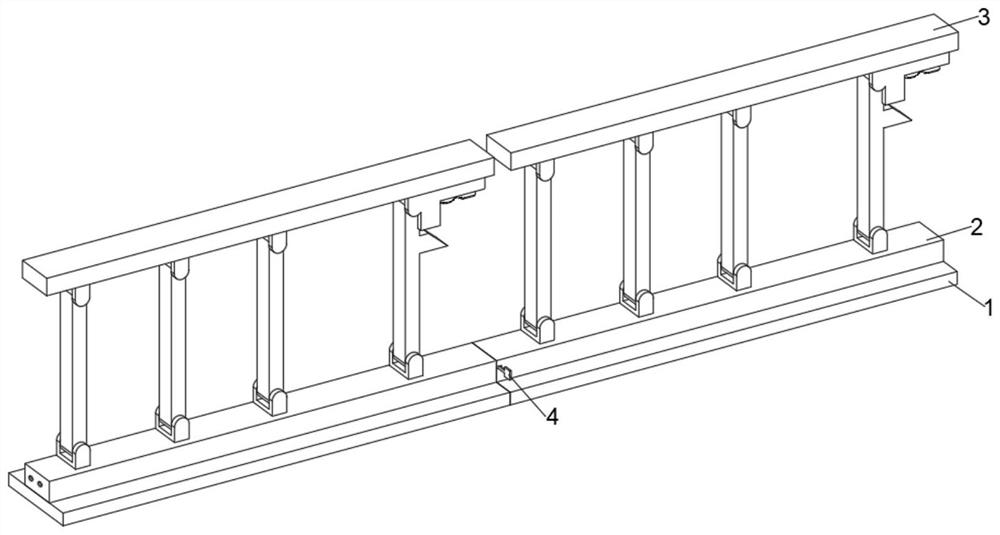
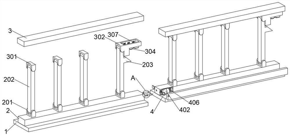
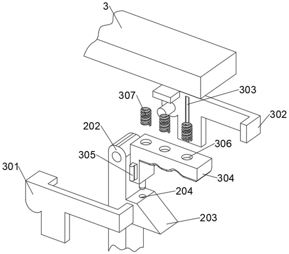
Novel multifunctional protective fence special for road and bridge green belt

A green belt and multi-functional technology, which is applied in the field of new-style multi-functional guardrails for road and bridge green belts, can solve the problems of destroying green belts and requiring staff to take a detour to the entrance and exit, so as to reduce workload and facilitate connection. , the effect of improving the efficiency of construction

Pending Publication Date: 2021-12-10
吴学峰
View PDF7 Cites 0 Cited by
  • Summary
  • Abstract
  • Description
  • Claims
  • Application Information

AI Technical Summary

Problems solved by technology

The prior art publication number is CN108797335B, which provides a novel multifunctional protective fence for road, bridge and green belts. The main body beam, the fixed base of the support frame and the support frame body are fixedly contacted and connected through the H-shaped clamping piece, the support frame body is fixedly contacted and connected with the concave connector, and the support frame body and the main beam are connected through the movable contact of the growth rod. The device can be adjusted Although the device has many beneficial effects, there are still the following problems: after the device is fixed by screws, it is necessary to reserve a fixed entrance and exit for the construction and maintenance of the green belt. Not only does the staff need to detour to the entrance and exit, At the same time, due to the reservation of the entrance and exit, pedestrians can easily enter and exit or will damage the green belt. In view of this, we propose a new type of multifunctional protective fence for roads and bridges green belts

Method used


Image

  • Novel multifunctional protective fence special for road and bridge green belt
  • Novel multifunctional protective fence special for road and bridge green belt
  • Novel multifunctional protective fence special for road and bridge green belt

Examples


Embodiment Construction

[0024] In describing the present invention, it should be understood that the terms "center", "longitudinal", "transverse", "length", "width", "thickness", "upper", "lower", "front", " Orientation indicated by rear, left, right, vertical, horizontal, top, bottom, inside, outside, clockwise, counterclockwise, etc. The positional relationship is based on the orientation or positional relationship shown in the drawings, and is only for the convenience of describing the present invention and simplifying the description, rather than indicating or implying that the referred device or element must have a specific orientation, be constructed and operated in a specific orientation, Therefore, it should not be construed as limiting the invention.

[0025] In the description of the present invention, "plurality" means two or more, unless otherwise specifically defined.

[0026] In the description of the present invention, it should be noted that, unless otherwise specified and limited, t...


PUM


Abstract

The invention discloses a novel multifunctional protective fence special for road and bridge green belts, and belongs to the technical field of road and bridge green protective fences. A novel multifunctional protective fence special for road and bridge green belts comprises a containing plate, the upper side of a first hinged support is rotationally connected with a supporting rod through a pin shaft, a clamping groove is formed in the middle of the upper side of a limiting block, a limiting frame is arranged at the right end of a second hinged support located on the right side, and a spring A is fixedly connected to the interior of a circular groove; through cooperation of the structures, the protective fences on the periphery can be put down through the design of the L-shaped handle and the limiting cam, construction and maintenance of a green belt are extremely convenient, the green belt can be directly constructed and maintained without detouring, the construction efficiency is improved, the workload of workers is reduced, and meanwhile when construction is not conducted or nobody exists, the construction efficiency is improved. The device can be automatically fixed after being lifted, is very convenient, and avoids the situation that pedestrians and the like can easily enter and exit or damage a green belt due to a reserved opening.

Description

technical field [0001] The invention relates to the technical field of road and bridge green protection fences, and more specifically, relates to a new type of special multifunctional protection fence for road and bridge green belts. Background technique [0002] The green belt refers to the strip for greening. It can eliminate visual fatigue, purify the environment, beautify the city, reduce traffic accidents, etc., and occupies an irreplaceable important position in the city. Separation of traffic by the green belt, with safety features. The green belt can beautify the city and eliminate the driver's visual fatigue. The planting of the arbor green belt can also change the spatial scale of the road, so that the road space has a good aspect ratio. In addition, it also has the effect of purifying the environment, can hold dust, reduce noise, absorb harmful gases, and release oxygen. The ratio of the width of the green belt to the width of the road should be appropriate. Th...

Claims


Application Information

Patent Timeline
Patent Type & Authority Applications(China)
IPC IPC(8): E01F15/04
CPCE01F15/0423E01F15/0484
Inventor 吴学峰
Owner 吴学峰
Why Eureka
Try Eureka